MoPi: Hot-Swap Mobile Power for the Pi
1. This is the OLD MoPi!
The new one is here!
MoPi is mobile, hot-swap and 24/7 power for the Raspberry Pi.
I want one! (how to order)
Something not working?
Raise an issue.
(In early 2014 we ran a Kickstarter campaign to fund the first production version, which was delivered in June 2014. If you missed it, you can get one from Pimoroni.)1
Contents
- 1. This is the OLD MoPi!
- 2. Pi to Go!
- 3. User Guide
- 3.1. Warnings!!!
- 3.2. Installation and Use
- 3.2.1. Quick Start
- 3.2.2. Installing the Software
- 3.2.3. Connecting the Power and the Pi
- 3.2.4. Turn On, Turn Off
- 3.3. Choosing and Configuring Batteries (Etc.)
- 3.3.1. Choosing Default Supply Profiles
- 3.3.2. Using the Configuration Tool on the Pi
- 3.3.3. Command Line, Python API and Daemon Config Hacking
- 3.4. Troubleshooting and FAQ
- 3.4.1. Wh...?
- 3.4.2. Pi Models: A, A+, B, B+, 2/B+, Zero, 3 (low current only!)
- 4. Background: Mobile Pi Power
- 4.1. The Prototypes
- 4.2. The Perfect Battery Pack
- 5. The MoPi Software Suite
- 5.1. simbamond, the simbamon daemon
- 5.2. The Python API
- 5.3. MoPi from the Command Line
- 5.4. Configuring Your Power Supplies
- 5.5. Monitoring
- 5.6. simbamon: a simple battery monitor
- 5.6.1. Design Notes
- 5.6.2. Implementation
- 5.6.3. Installing simbamon
- 6. How it Works: the Hardware
- 7. Testing
- 7.1. The Longer-Lasting Snack
- 7.2. Battery life
- 7.2.1. Battery life under load
- 7.2.2. What the sun says
- 7.3. Methods in the Madness: Debugging and Software Development
- 8. In the Wild: Applications
- 8.1. Outdoor Adventure Kit
- 8.2. Outdoor Experimenter Kit (Light)
- 8.3. Outdoor Experimenter Kit (Light and Air)
- 8.4. Kickstarter Backer Projects
- 8.4.1. Night Camera
- 8.4.2. K9
- 8.4.3. Self-Balancer
- 8.4.4. Garden Camera
- 8.4.5. Remote Switch
- 9. Batteries, Holders and Chargers
- 10. Other Directions
- 10.1. A Possible Charging Circuit
- 10.2. Other Options
- 11. Linux is Lovely
- 11.1. Glitches in the Pi's I2C Bus
- 11.2. Installing I2C
- 11.3. Debugging with I2C Tools
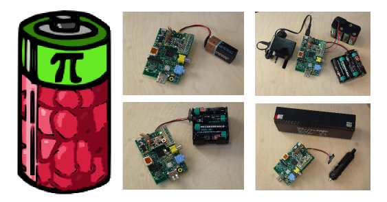
2. Pi to Go!
MoPi is mobile and 24/7 power for the Pi. On your bike, up a tree, or for your home server: we've got you covered.
![]()
Features:
- multiple inputs — standard batteries, car power sockets, old laptop supplies, solar panels, and more... all attachable via standard screw terminals
- hot-swap power replacement without stopping work
- shutdown the Pi cleanly when batteries discharge
- integrated on/off switch
- usable as a UPS (uninterruptible power supply) by attaching both batteries and mains
- on-board LED indicators and on screen linux system notifications
- configuration of multiple battery chemistries and number of cells from a UI on the Pi
- full API in Python, plus a shell-friendly command-line interface
- stackable headers allowing connections of multiple boards at once (e.g. MoPi + XLoBorg, or MoPi + AirPi, or etc.).
- PCB remoting pads for the power switch
- self-resetting fuse for over-current protection
- two-way communication via the I2C bus
- remote power-off: tell MoPi to power down the Pi when logged-in remotely (after a clean shutdown, of course)
- timer-based wake-up: tell MoPi what time you want your Pi to wakeup, then power it down and MoPi will boot the Pi as requested
- 3.3V supply mod: swap three resistors and supply 3.3V, overpowering the Pi's on-board regulator and saving the power that is dissipated there, for weight and battery life critical applications like ballooning
- supports Pi models A, B, B+, Zero and Pi 3 (but the latter at low current only)
- wide input voltage range: 6.2V to 20V2
And it even fits in the Pibow (and other well-known Pi cases):
3. User Guide
3.1. Warnings!!!
- DO NOT plug MoPi onto your Pi while the Pi is powered up!
- DO NOT touch electronic components when they're powered up — you may damage them, or burn your fingers!
- AVOID handling circuit boards when charged with static!
- ALWAYS read the small print on all components supplied with your MoPi
- ALWAYS treat batteries and other power supplies with respect — if abused the energy they contain may surprise you in dangerous ways!
- DO NOT feed MoPi to your dog, eat nuts if you're allergic to them, or lose your sense of humour.3
3.2. Installation and Use
3.2.1. Quick Start
If you're in a hurry:
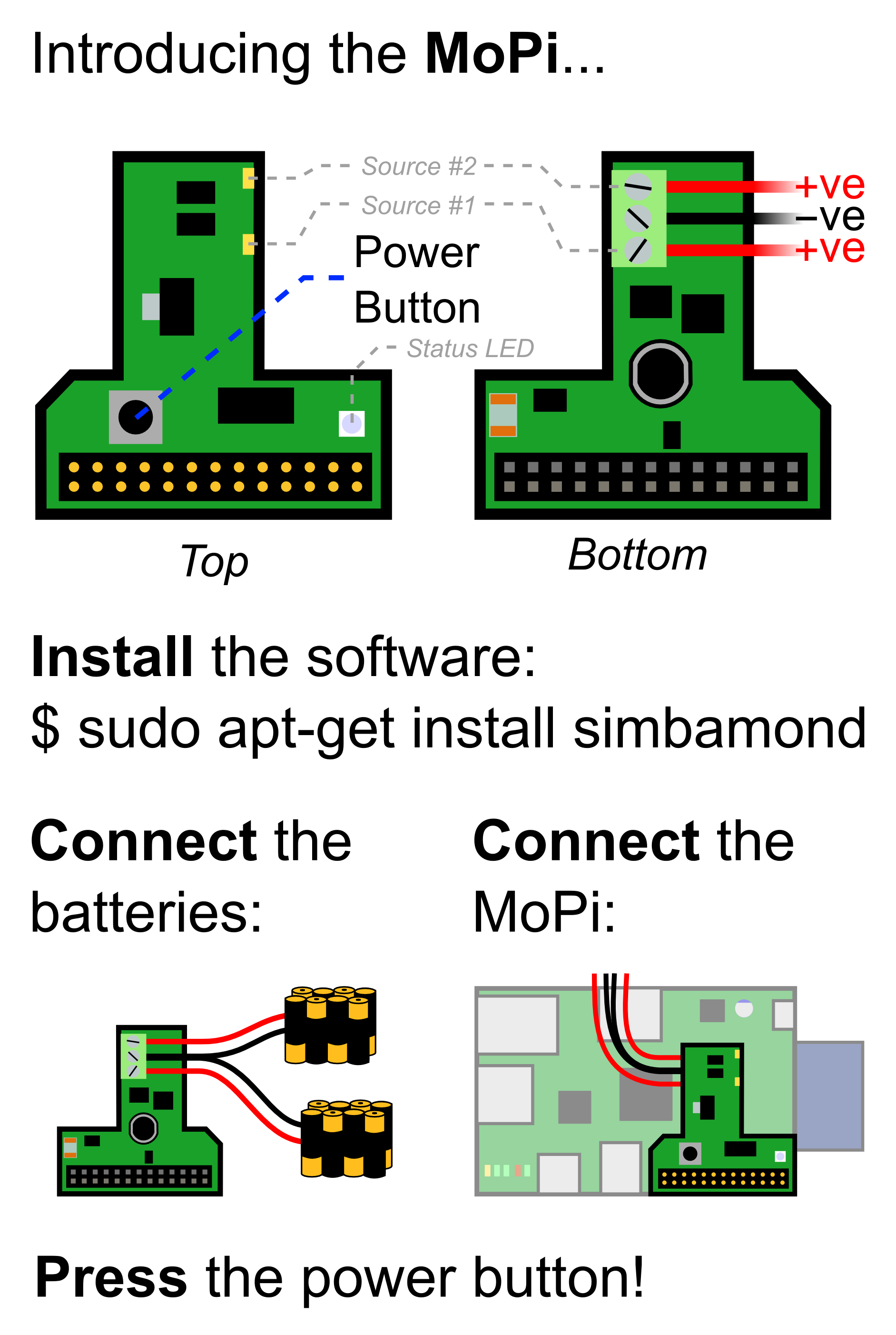
- Install the battery monitoring software and shutdown:
- sudo apt-get update
- sudo apt-get install simbamond4
- sudo poweroff
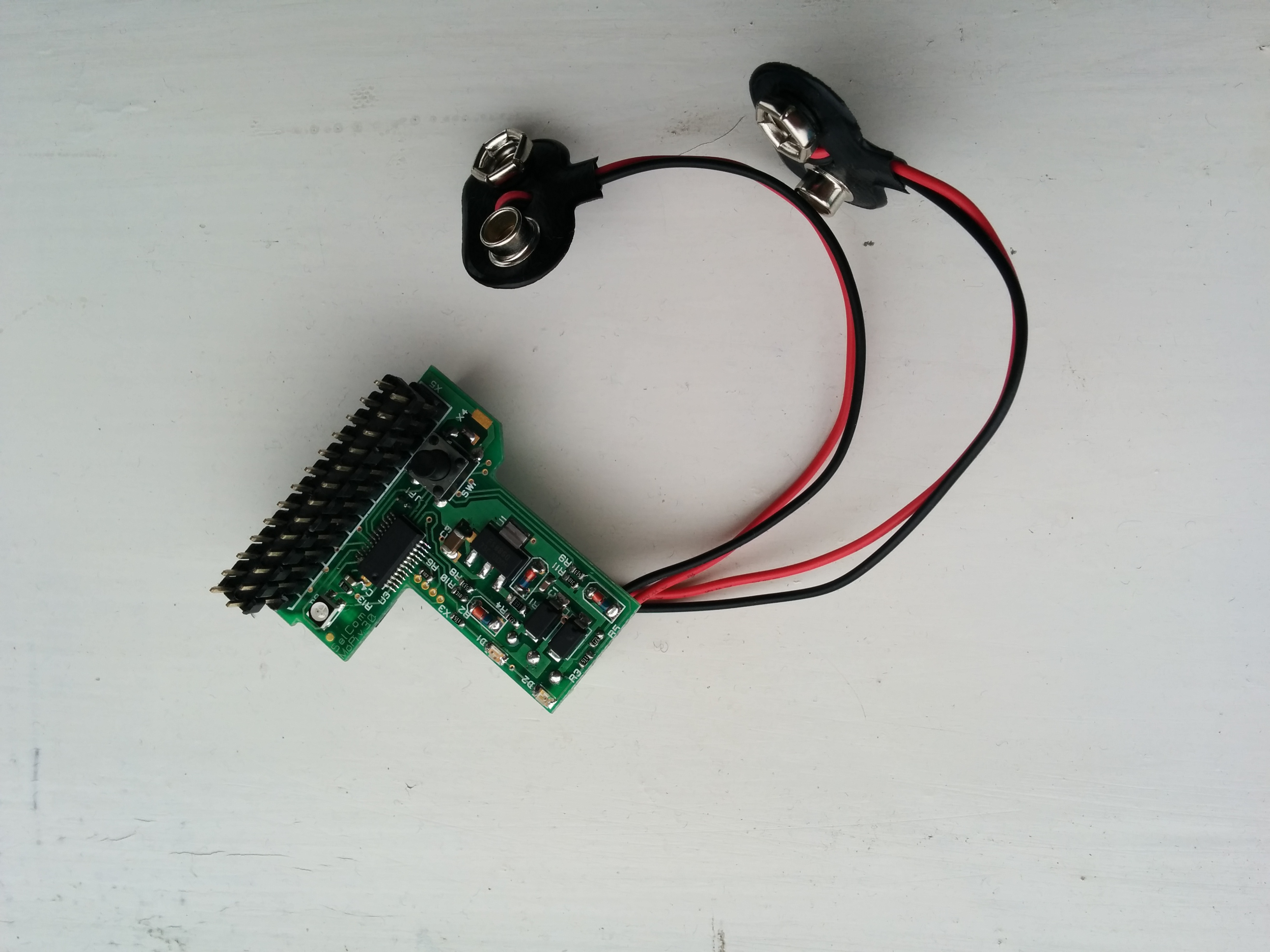
- Connect your batteries to the MoPi
- Attach the MoPi to your Pi and press the Power Button for 3 seconds
For more details on each step, see below.
3.2.2. Installing the Software
As noted above, you can install the battery monitoring software like this:
- sudo apt-get update
- sudo apt-get install simbamond
(We assume you're using the Raspbian flavour of Debian GNU Linux here.)
Occasionally this method may cause glitches (if you've a very old version of the rest of the operating system installed, for example). The most cautious recipe is to update your firmware and the operating system, then install the MoPi software, and to reboot between each step:
- sudo apt-get update
- sudo apt-get upgrade
- sudo reboot
- sudo rpi-update
- sudo reboot
- sudo apt-get install simbamond
- sudo poweroff
Note that if you're installing the software without MoPi attached, or without power attached to MoPi, you will get a warning message5; just ignore it at this point!
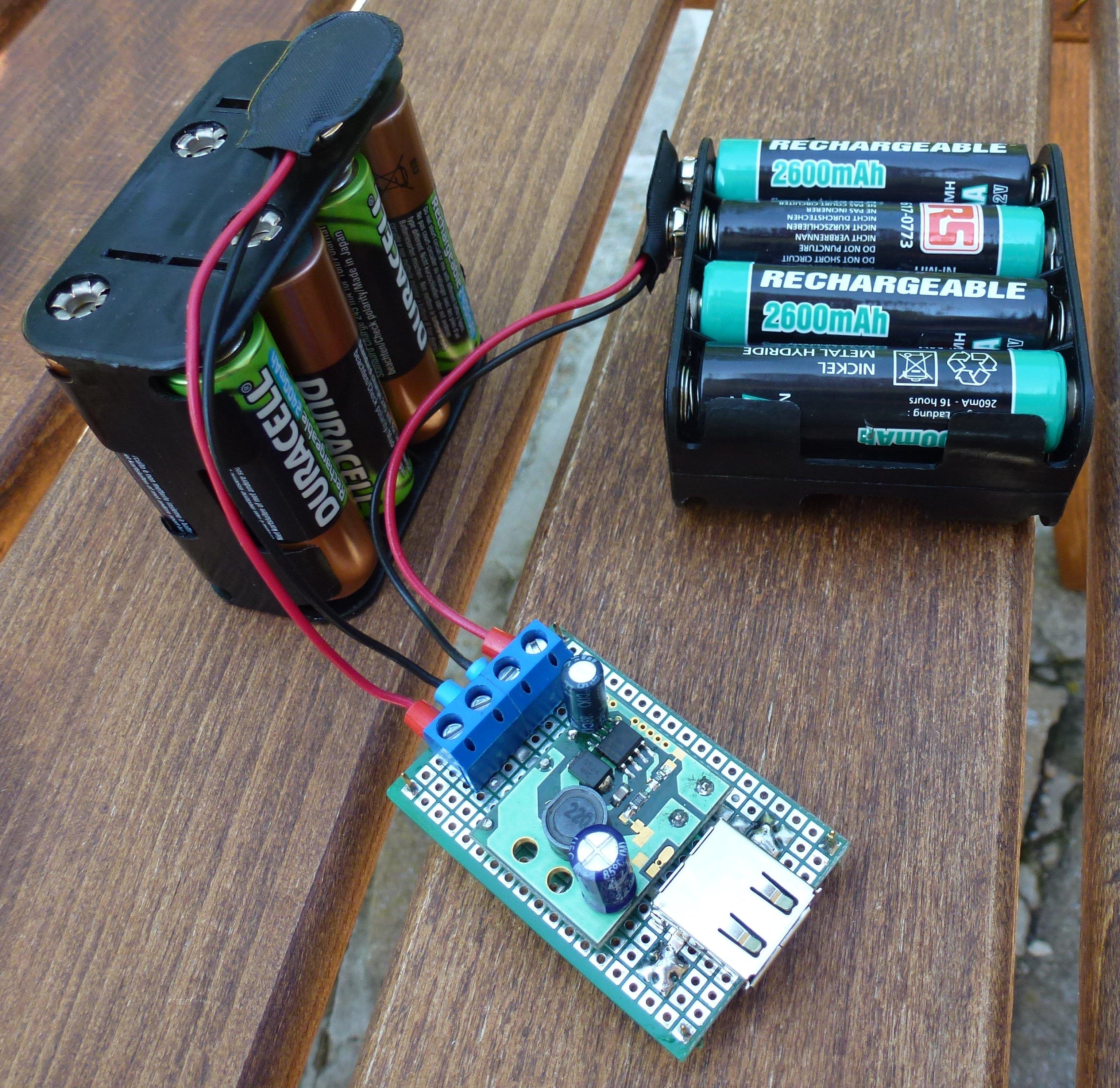
3.2.3. Connecting the Power and the Pi
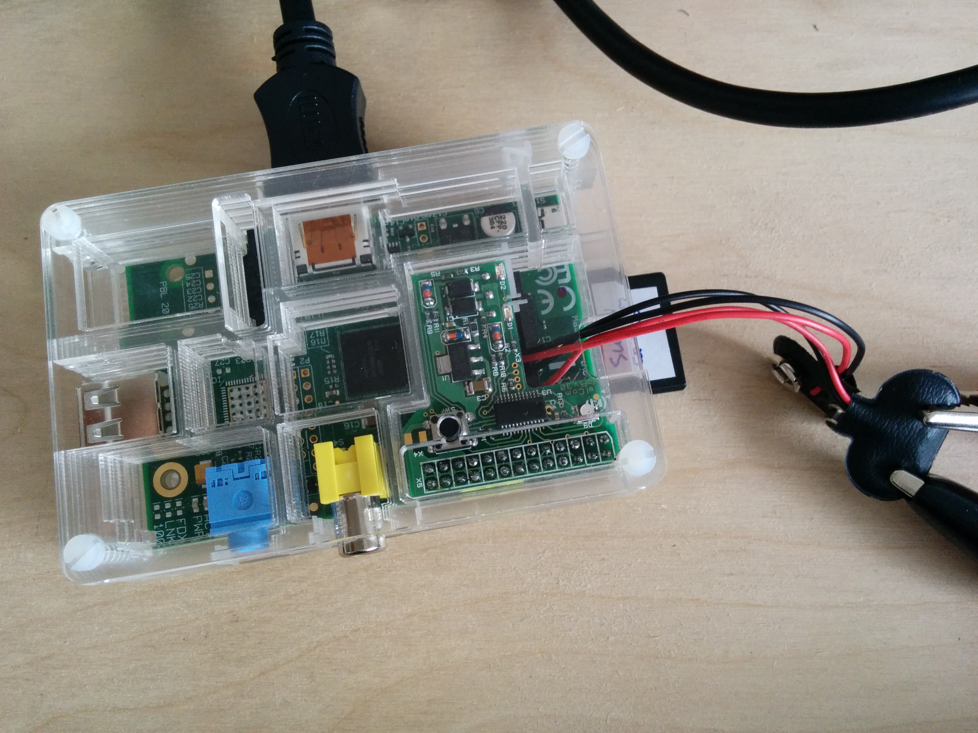
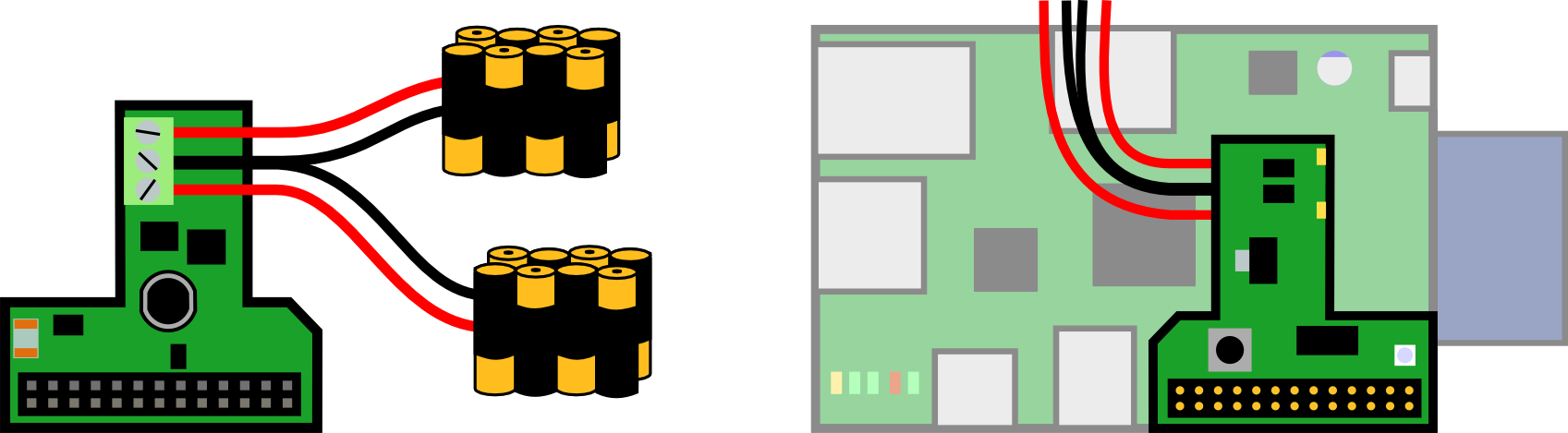
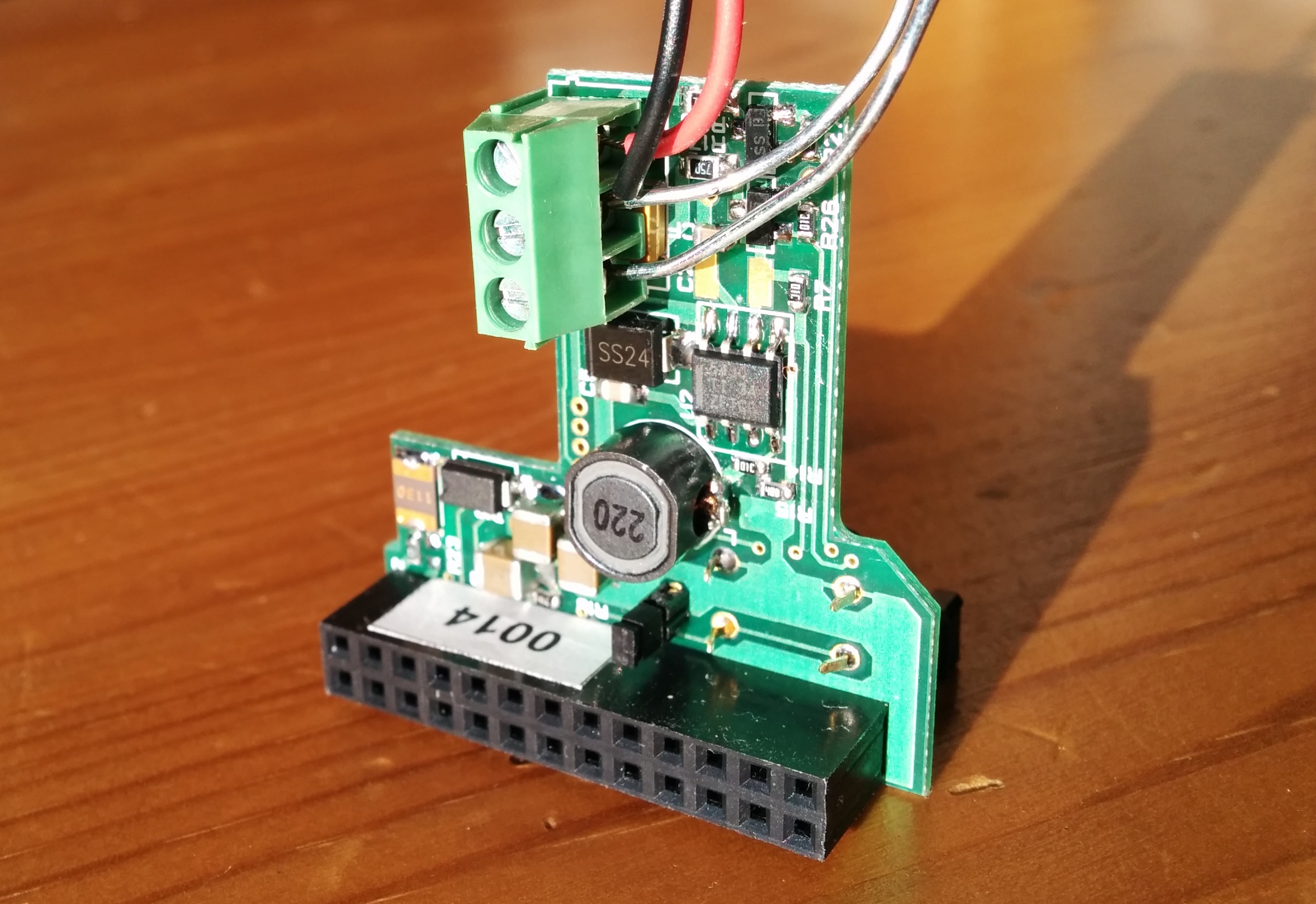
Next connect one or more power supply to MoPi using the screw terminals on the underside of the board. Then gently push fit MoPi onto your Raspberry Pi's GPIO pins. Make sure you do this with the Raspberry Pi turned off, or you risk a reset.
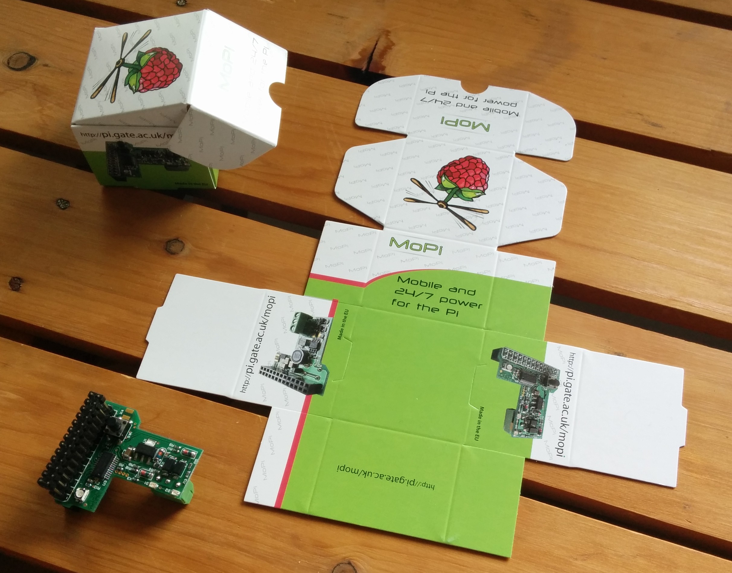
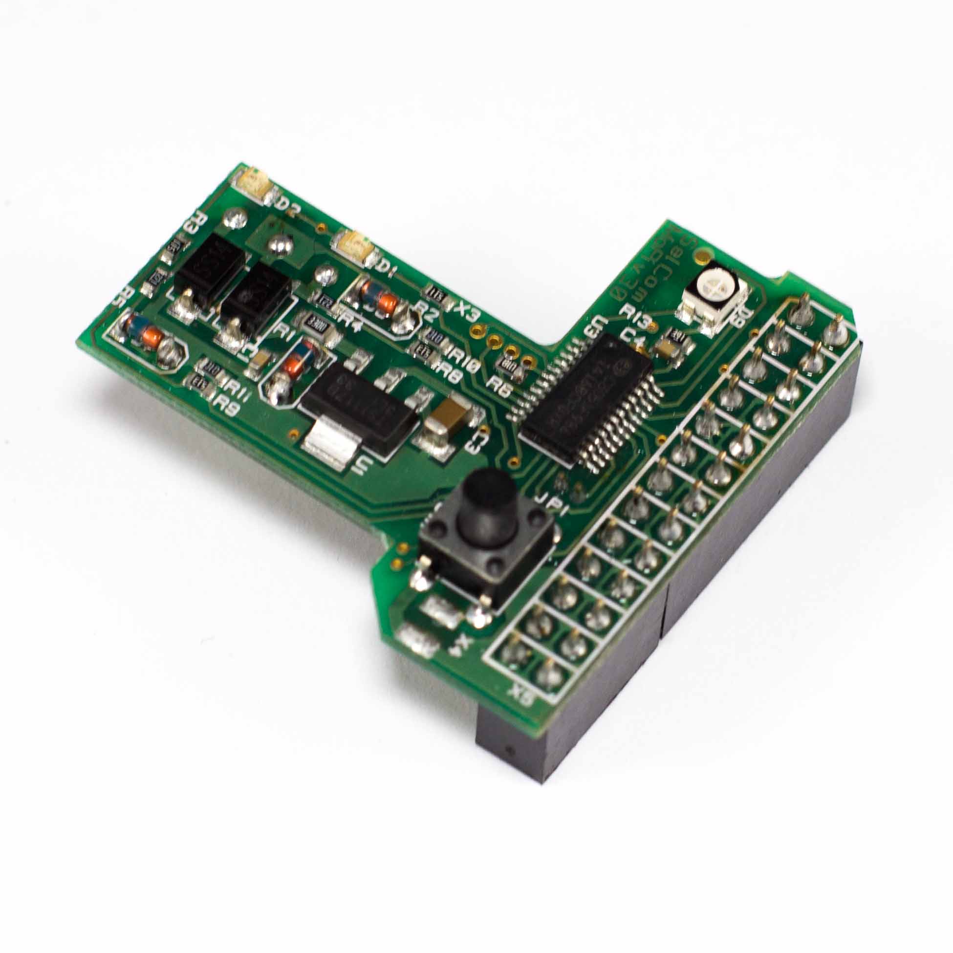
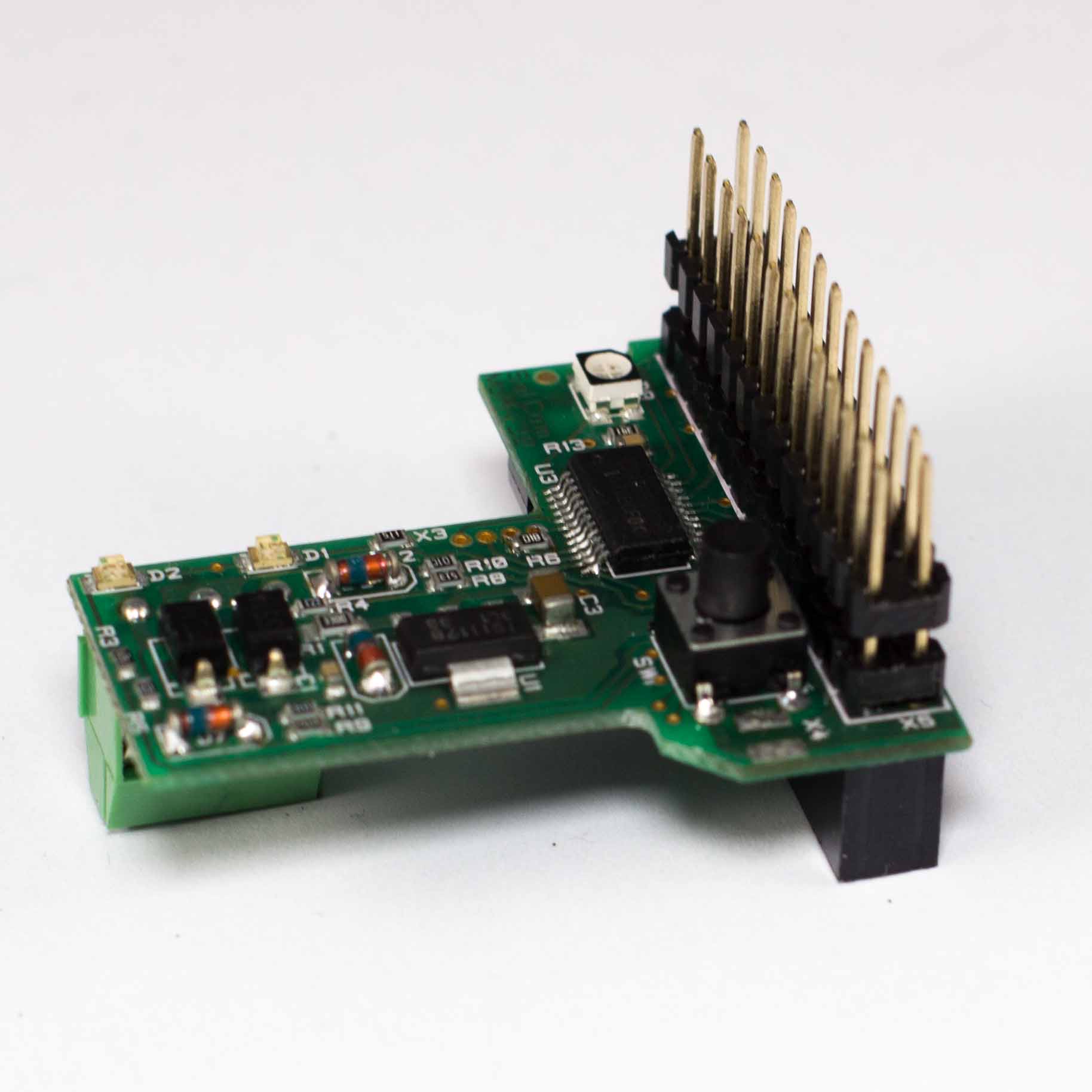
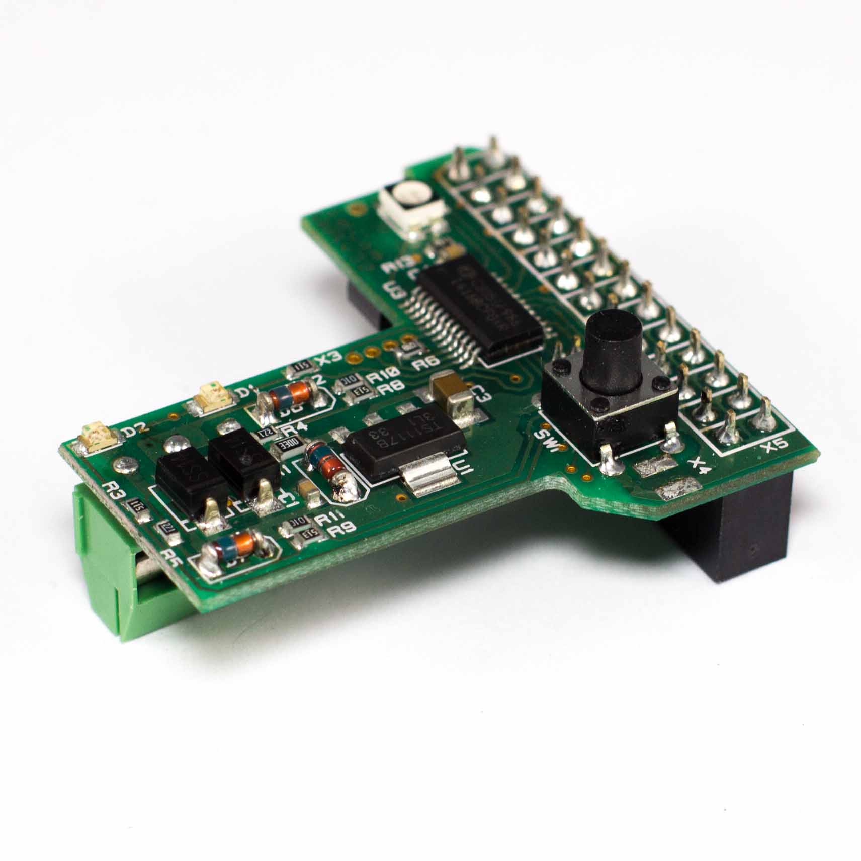
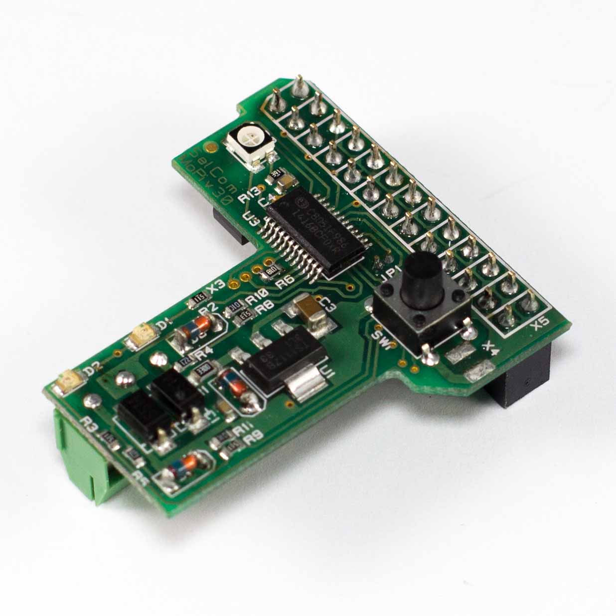
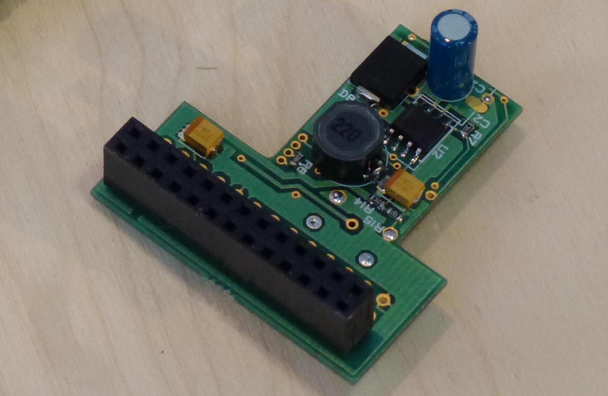
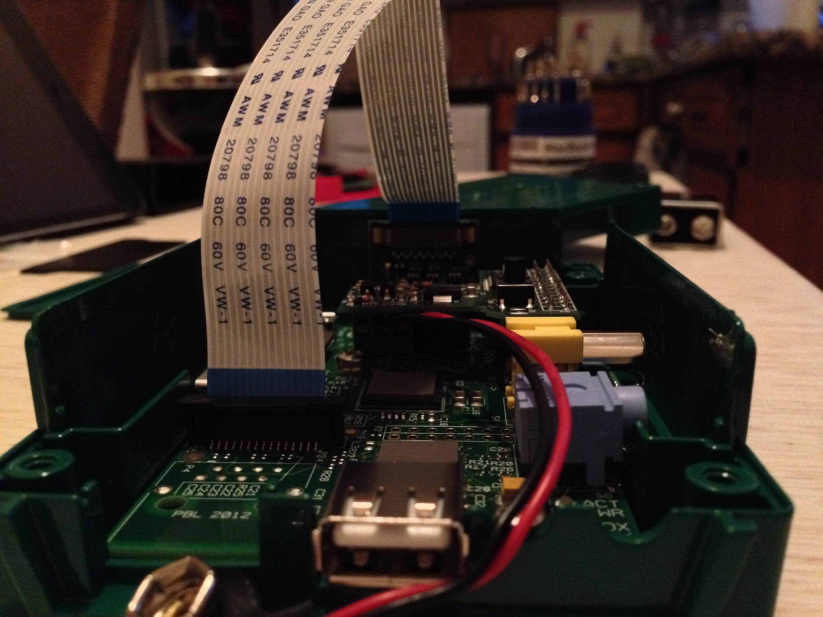
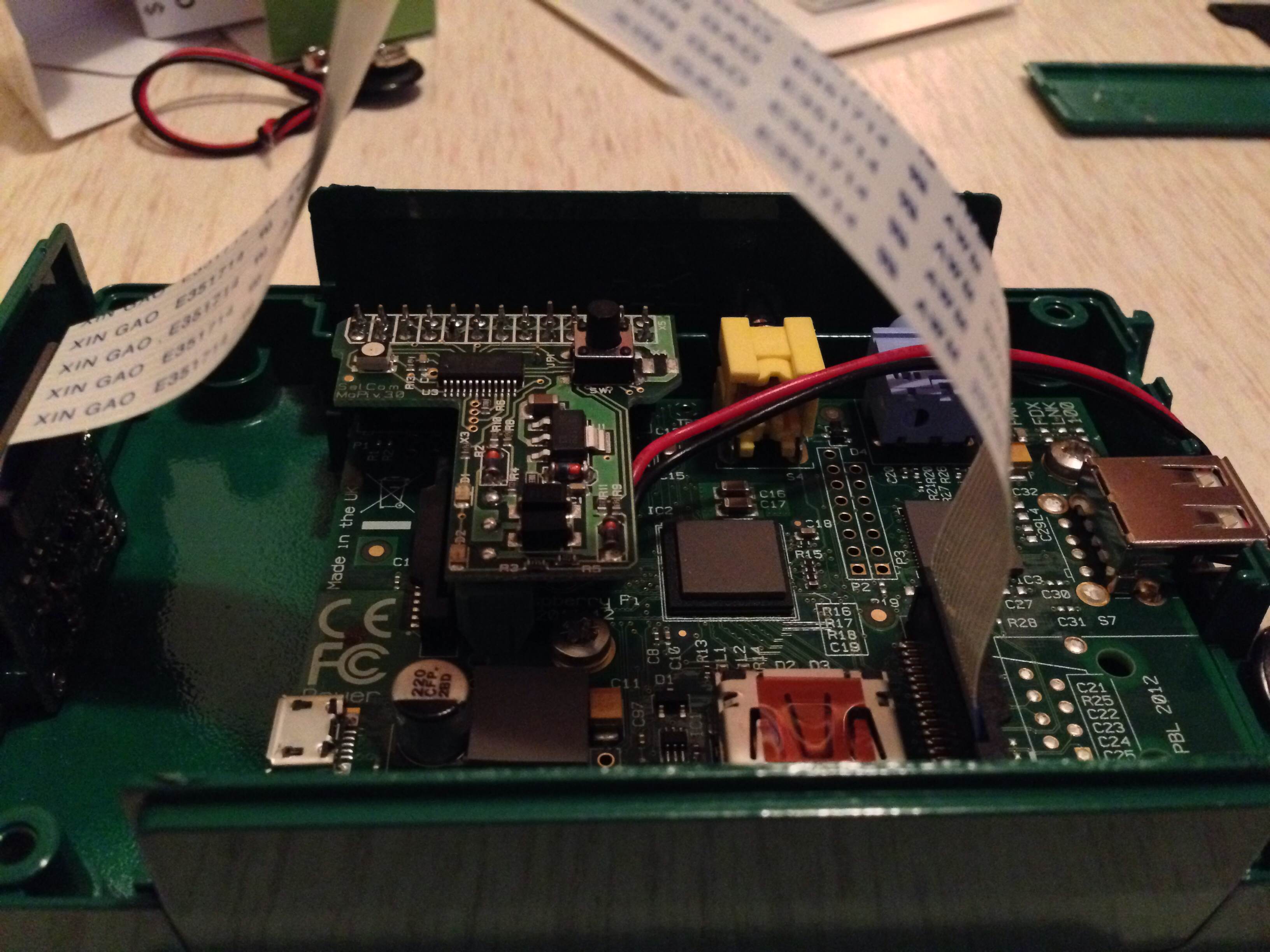
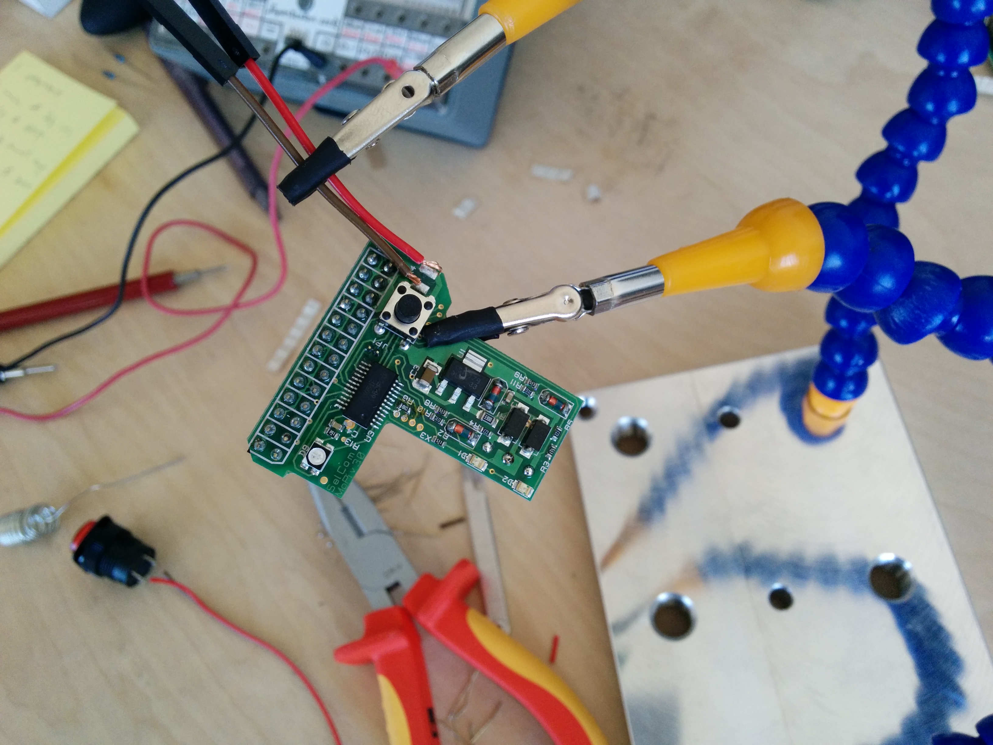
The components on the MoPi are as follows:
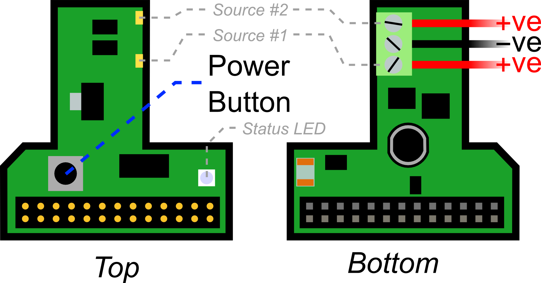
When connecting two power sources (e.g. two battery packs, or one solar panel and one battery pack) the ground wires (-ve, typically black) both share the middle connector on the screw terminals. The live wires (+ve, typically red) then get one each of the other connectors. The lower of the supply connections shown in the schematics corresponds to source 1; the other to source 2.
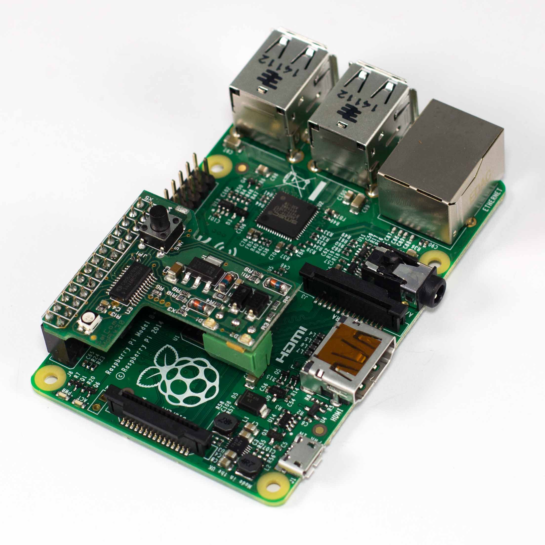
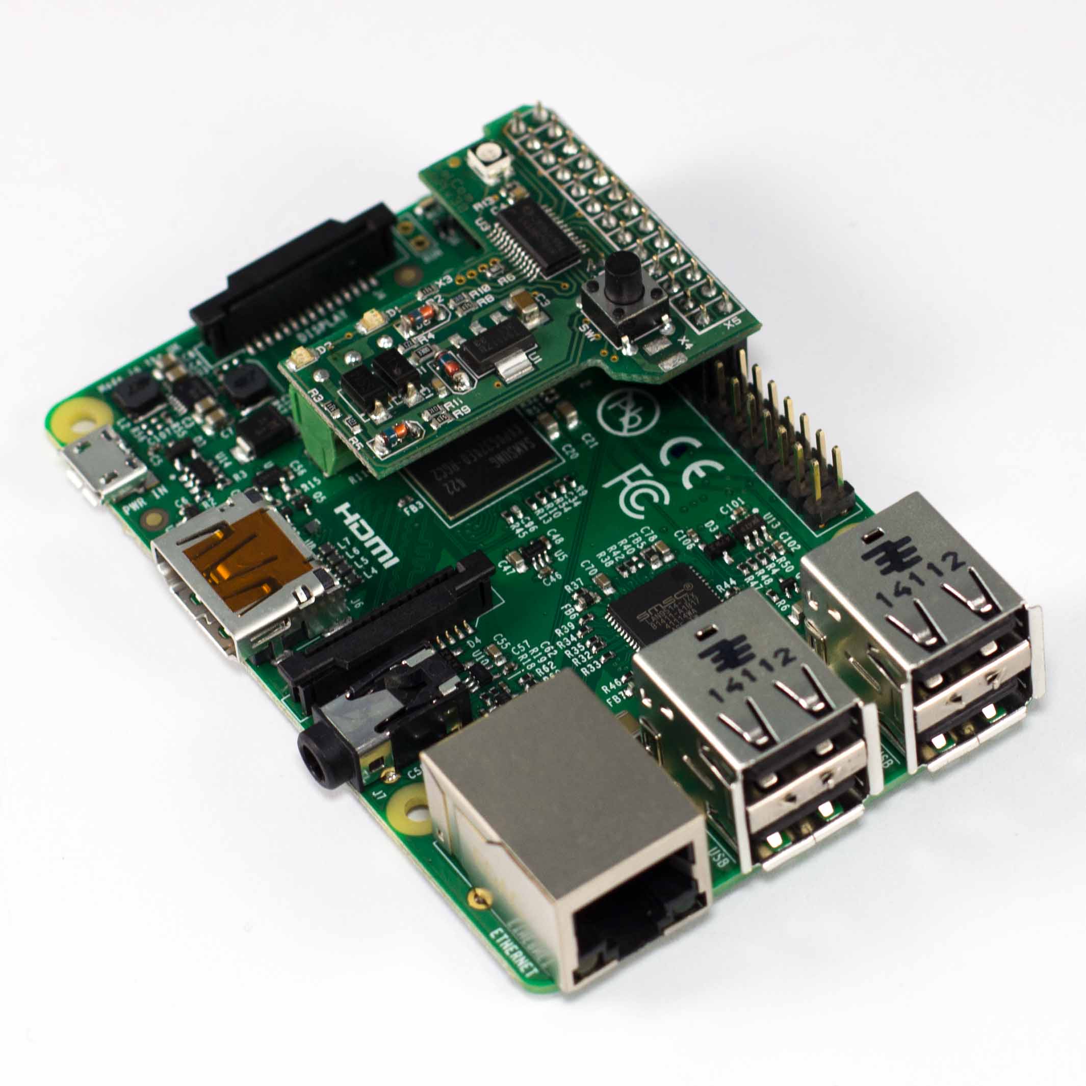
When you've connected your supplies, MoPi then fits onto the Pi as shown on the right:
The charge level of each source is signalled by the two amber LEDs on the top of the board, and the overall health of the supplies by a single RGB6 LED.
3.2.4. Turn On, Turn Off
When the Pi is powered off, press the power button for 3 seconds to turn it on.7
When the Pi is powered on, press the power button for 3 seconds to turn it off. This will shut the Pi down cleanly (which can take up to around 30 seconds). If you hold the power button down for 10 seconds, the power will shut down immediately.
3.3. Choosing and Configuring Batteries (Etc.)
The short story is this:
- Any power supply connected to the MoPi must be capable of at least 6.2V under load, and no more than 20V.
- The MoPi must be configured correctly both to avoid damage to rechargeable batteries and to avoid unexpected shutdowns!
How do I configure MoPi? There are 3 ways:
- Choose one of the on-board defaults—easy peasy!
- Use the Configuration Tool8 on your Pi—straightforward.
- Use the command-line interface, and/or edit the daemon config data on your Pi—advanced.
Let's take each of these in turn...
3.3.1. Choosing Default Supply Profiles
MoPi has two default supply profiles built-in:
- Non-rechargeable or non-battery supplies.
- Eight NiMH AA rechargeable batteries.
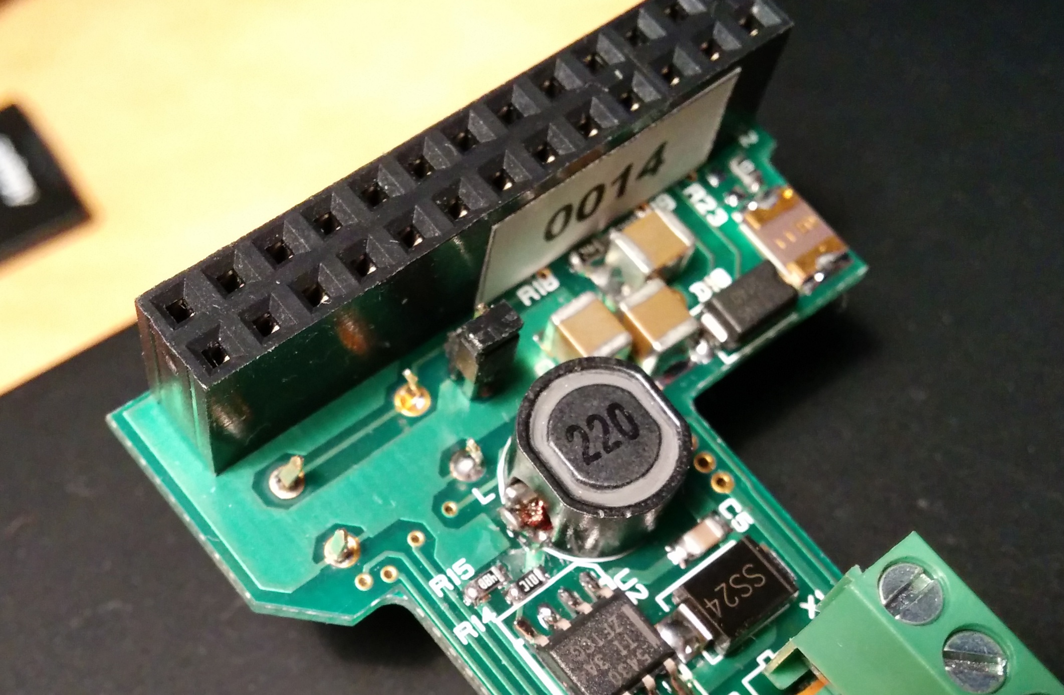
The default is #1, so that any supply can power the MoPi. To choose #2, you need to remove the small jumper on the screw terminal side of the MoPi, either completely or replaced on only one of the pins.
Note: when we supply MoPi with batteries we fit the jumper to choose profile #2, that is so it matches NiMh the batteries we shipped!
You can see the jumper in this picture: the little black component sticking up and overlapping with the right hand end of the white sticker on the GPIO connector (labelled 0014):
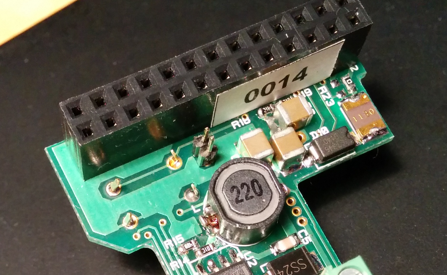
Here's a closer view:
Now here's what it looks like when you remove the top to select profile #2:
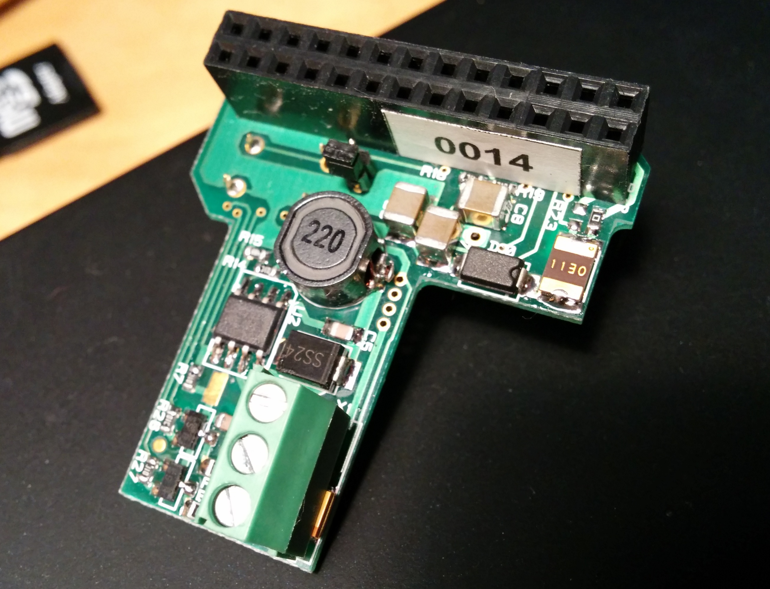
And here's the top of the jumper replaced on only one pin, again selecting profile #2: This is useful to avoid losing the tiny little thing!
3.3.2. Using the Configuration Tool on the Pi
If you're using a supply that doesn't match MoPi's two built-in profiles you need to run a configuration utility on the Pi itself. This will prompt you to enter details of the supply, then calculate appropriate values to send to the board over I2C. It will also store the config data and resend it to the board after reboots as necessary.
To start the configuration tool open a terminal and do:
sudo mopi
The tool operates in the same way as the Raspberry Pi's configuration tool (raspi-config). Select the option to configure one or both of MoPi's supplies, and then:
- Type of supply. This is one of rechargeable battery, non-rechargeables (like standard Alkaline batteries), or non-battery (like an AC adapter, or 50kW wind turbine, or hydoelectric dam, or electrical delusions of grandeur).
- Number of cells. This is the number of individual battery cells in your supply. Note that some batteries incorporate several cells — e.g. a 9V PP3 has 6 cells internally. If you're not using batteries select "1". We shipped out sets of 8 NiMH batteries; if you were using those you would select 8 here.
- Battery chemistry. The type of battery you're connecting. For example "Alkaline" or "NiMH" (or "N/A" for non-battery supplies).
After entering this data the tool will give details of the values it has calculated and offer to write these to the MoPi board. There is detail of these values and how the tool works below.
3.3.3. Command Line, Python API and Daemon Config Hacking
Finally, if you want more control, or the other methods are insufficiently scarey, you can use the command-line tool directly, or edit the simbamon daemon configuration data, or write code using the Python API.
A quick demo of using the cli setting the default 8 NiMH profile:
sudo mopicli -wc 1 11200 10000 8800 8000
For more details, see the software below.
3.4. Troubleshooting and FAQ
3.4.1. Wh...?
>>> Which GPIO pins does MoPi use?
As of version 4 (the Kickstarter version) MoPi uses these pins:
- pin 2 (and/or pin 4): 5V out
- pins 3 and 5: i2c bus
- pin 6 (or any other grounded pin): 0v
(For a good Pi pinout diagram see the WiringPi site.)
>>> I get a warning during software installation
If you're installing the software without MoPi attached to the Pi, or without power attached to MoPi, you will get this warning message:
/usr/sbin/simbamon: /usr/sbin/mopicli not working; MoPi not attached or powered? (mopicli. I2C bus input/output error on read word. Check bus? Check connection?)
In this case you can safely ignore it.
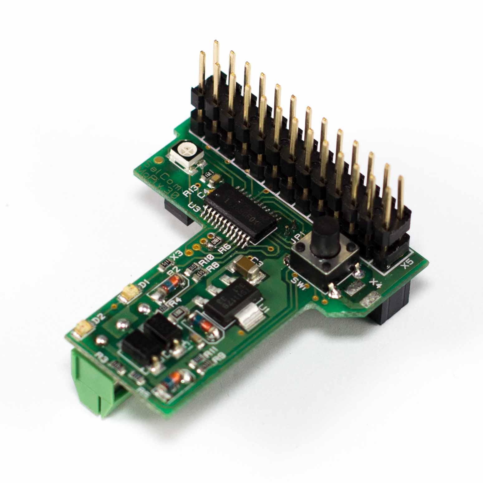
>>> Should I get a stackable header or a low-profile one?
>>> What if the power switch isn't accessible?
If you want to fit your MoPi into tight spaces, you probably want a small (low-profile) header. If you want to stack MoPi with other Pi add-on boards, then you want a big, "stackable", header.
Note that if you do get the stackable version, when you put another board on top of MoPi it may hide the power switch and/or the LEDs. In the case of the power switch there are solder pads on the PCB, right next to the button, to allow fitting of a remote power switch.
>>> How do I connect another board?
If you want to use MoPi in combination with another Pi add-on board (e.g. AirPi) you need a) to have ordered the version with stackable header pins, and b) to remove the plastic collar that the board is shipped with to prevent bending. Then the other board will just slip down onto the MoPi headers just like those on the Pi.
If you've got a low profile MoPi (without the stacking pins) don't despair — if you other board has stacking pins then MoPi can go on the top (which is better, in fact, as you'll be able to access the power switch too!).
MoPi should be compatible with all other Pi add-on boards, as we only use the I2C bus, which supports the connection of multiple devices.
>>> I connected a power source but MoPi won't start...?
MoPi needs a minimum of 6.2 volts to run. Then it also has a (configurable) "safe depth of discharge" setting to prevent damage to rechargeable batteries. If the sources connected aren't higher than the highest of these, MoPi will refuse to power the Pi. (If there is enough voltage to run the microcontroller, it will blink the relevant amber LED a few times to signal the problem.)
Solutions:
- Ensure that the Jumper that selects the default battery profile is set for profile #1 (non-rechargeable) as this lets the MoPi power on under the most conditions. Be aware though that you may damage your rechargeable batteries if you don't configure the MoPi for them in software on boot, so make sure you've appropriatly...
- Configure the MoPi to accept the supply (if it will reliably exceed 6.2 volts under load).
- If it still doesn't start, the batteries may be discharged! Connect some freshly charged ones or a higher voltage supply.
Sometimes the reported voltage for a particular source seems to be high enough to drive the Pi, but MoPi considers it too low — why? When a new source is connected it is shunted through a simulated load for a few tenths of a second. Batteries drop their voltage under load, and the lower their level of charge, the larger the drop. MoPi measures the voltage under load, and if it is too low it will refuse to use that supply. After disconnecting a power supply, wait a few seconds before connecting a new one so that the MoPi registers the disconnection and will re-test the newly connected battery pack.
>>> What type of regulator chip is it? What is the voltage range?
MoPi uses a switched-mode regulator (a TPS5430 or TPS5430), so almost no power is wasted.
The input voltage range is 6.2V to 20V. There's no step-up circuitry so the battery or solar panel rig or etc. has to supply 6.2V at minimum. Consider connecting multiple batteries or panels in series to increase voltage.
>>> Is it safe to bypass the Pi's built-in fuse?
Yes — in this case...
The issue: MoPi supplies power to the Pi over the GPIO pins, instead of via the micro USB connector (which it leaves free so that mains power can be plugged in at the same time as batteries if required). The 5V feed from GPIO involves bypassing the Pi's built-in fuse (which is in line with the USB connector).
Is this safe?
Given a correctly functioning Pi and peripherals, then the answer is a clear "yes". But what about if the Pi is faulty, or if a pin is shorted out, or if someone connects a 3 bar electric heater to it? :-)
Three considerations:
First, MoPi is currently capable of supplying 1A, after which there is an internal current limiting circuit. It uses standard voltage and power regulation circuitry which is robust and mature, and will not allow over-volt or over-current on the output.
Second, we're supplying from batteries, not mains — so as long as we don't over-consume from the battery (which in principle we can't short of a major internal fault) there's a limit to the amount of power we can supply to a faulty Pi.
Third, not having an internal fuse is pretty standard behaviour — poke around in the electronics of all those power supplies sitting around in your desk drawer and you won't generally find fuses.
Having said that, we added an autorecovery fuse to version 3 just to be ticking all the boxes. ;-)
>>> Can I access the voltage data on MoPi from the Pi?
Yes!
The software on the Pi that talks to MoPi, simbamond, is open source and available here: https://github.com/hamishcunningham/pi-tronics/tree/master/simbamon (See also http://pi.gate.ac.uk/pages/download.html.) The Raspbian maintainers have added simbamond to their repository, so you can install it in the same way as any other Pi sofware.
Simbamond listens to MoPi and logs the data in a standard manner, which other applications can then consume as required. There's also a Python API and a command-line interface (CLI):
sudo mopicli -v -v1 -v2
For more details, see the software below.
>>> Can I combine mains and solar power?
Yes!
This should work so long as you connect the mains-derived power to one of MoPi's inputs (it will have to be a supply >= 6.2 volts). MoPi will then use mains whenever the solar output dips below the mains supply. The ideal would be a solar panel rig that outputs e.g. 15v coupled with a 12v mains supply, or some similar config.
Note also that the Pi will draw significant current, depending on the model and the peripherals, and you will needs sufficient panels (and sunshine!) to generate the requisite power. As a very rough guide, we've had some success with two 10W panels running a model B (without peripherals).
(We're running a rig now in the workshop that has two 18V panels in parallel; watch http://pi.gate.ac.uk/ and we'll post the results!)
>>> How do we avoid deep discharge of rechargeables?
The short answer it to shutdown before it happens. Rechargeable batteries don't like being completely discharged. We always need to stop drawing from the battery at some distance above some minimum voltage level. This level varies for different battery chemistries (NiMH, LiPo, lead/acid, etc.) and for different numbers of cells (eight AAs vs. two PP3s vs. one car battery, etc.).
MoPi listens continuously to the voltage level on the battery inputs. How does it know when that level is getting low? Let's identify two separate low-level points: first, the absolute low voltage level is the point where our micro-controller can no longer reliably run the switching regulator to produce a constant 5V (around 6.2 volts). The second low voltage (critical) point is just above the deep discharge level, which depends on the batteries attached. When you use the configuration tool this critical voltage point sent to the MoPi. As long as you've correctly configured your batteries, we should be avoiding deep discharge.
When the MoPi decides the input voltage is critical (for either or both of its two supplies), simbamond warns the user and shuts down the Pi cleanly (from software first, using "sudo halt", and then by cutting power). How do we decide when to do this, that is to say, how do we pick the critical voltage level? We've done some research on batteries. For eight NiMH 1.2 volt cells the critical voltage is around 8 volts. For non-rechargeables, or solar panels or a water turbine, it is the same as the absolute low level (6.2V) as these can't suffer deep discharge.
Be aware though that be default the MoPi assumes that standard non-rechargable battires (e.g. Alkalines) or an AC adapter have been connected, which sets the critical voltage level to 6.2V. This is to get you off the ground, as the MoPi will power on with almost anything attached like this. However, on boot the MoPi must be configured correctly for your batteries or you risk damaging your batteries through deep discharge, which is what we're trying to avoid. This default is selectable though through our two default profiles. If you recieved batteries from us (the "battery heaven", UPS and outdoor kit rewards) your MoPi will instead by default be configured for 8 NiMH AA cells.
The critical voltage level is kind of short notice though for replacing batteries. The configuration tool also specifies a low voltage level, which is when the LED on the MoPi turns red and you start recieving low battery notifications. This is set to be 1.1*critical, so for 8 AA NiMH batteries it's 8.8 volts. (There are other voltage levels defined too. Read more later.)
>>> How do I modify it to produce 3.3V?
- Take out R22.
- Solder this resistor on position R23.
- Replace R15 with 5.6 KOhm 1% 0603 size.
>>> Mkmod or libkmod errors when installing or upgrading.
The installation of simbamond requires enabling i2c. There are two ways to do this, depending on what version of Raspbian we're running. At present the installation script tries to do both, with the intention of catering for the maximum number of variants. This does mean that you may see errors like the following. If everything works after a reboot, ignore them; otherwise:
- try installing i2c-tools and i2cdetect to see if the bus is enabled
- i2cdetect -l will return nothing if i2c is not enabled, or something like "i2c-1 unknown ..." if it is enabled
- raise an issue.
If you get a message like "libkmod: ERROR ../libkmod/libkmod.c:554 kmodsearchmoddep: could not open moddep file '/lib/modules/3.6.11+/modules.dep.bin'" when installing try a reboot followed by "sudo apt-get -f install".
>>> The I2C bus doesn't work after install.
If the I2C bus appears not to be working after installing simbamon, try a reboot. Sometimes the Python SMBus module appears not to load correctly.
>>> How do I add a remote power switch?
There's a description here.
>>> What do the status bits mean?
MoPi returns status data to the Pi over i2C — if you need to interpret these:
- mopicli -sv will give you the decoded status
- check the source code to see the meaning of each bit
>>> How do I ...?
Another good place to look is the GitHub issues list (click on the "closed" list to see them all).
If you're still stuck, raise a new issue?
Good luck!
3.4.2. Pi Models: A, A+, B, B+, 2/B+, Zero, 3 (low current only!)
MoPi will work fine with the Raspberry Pi models A, B, the Model B Plus Pi, the A+, and the Model B 2. It will also run the Pi Zero, but it only runs the Pi 3 at low current levels. If you're a stickler for detail you may want to shim the terminal connector to raise it over the CPU in its new position on the Model 2 and the A+. (MoPi++, version 5, scheduled for release in 2017, is specifically designed to support the Pi 3.)
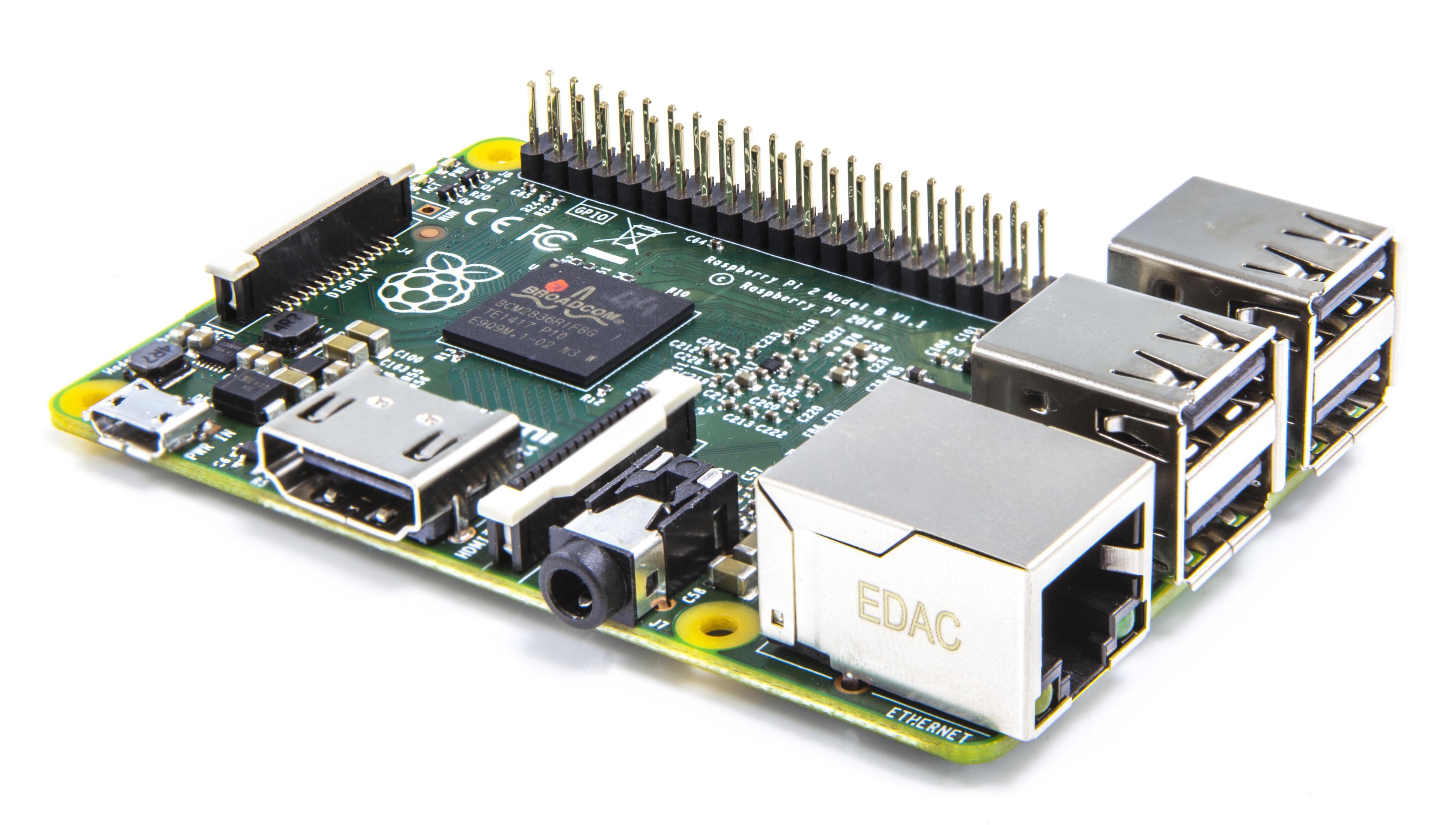
And here's MoPi on the Pi 2! (Why didn't they call it the Model C though?!) The Pi 2 was released in February 2015, and looks like this:
Prior to version 2, the Model B+ was released, as an evolution on the original Model B; it looks like this:
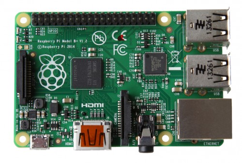
From a mobile power point of view the B+ performed a bit better than the B — they replaced the rather wasteful LDO regulator of the original with a switched-mode supply, and with the revamp and extension of the USB subsystem they've also improved power handling there.
And the good news is that there's no issue with the new CPU position on the B+. MoPi's connection terminals actually sit on C1 (a large capacitor near the CPU), and not on the CPU itself. You can see this here:
So we're good to go — initial indications are that the B+ is an even better platform for mobile power (and MoPi) than the Model B...
PS If you fire up a B+ with an operating system you've been using on one of the older models, you may discover that e.g. your USB keyboard doesn't work: you need the most recent operating systems to run the B+. One easy way to get one is to download a new copy of NOOBS and unzip it onto a micro-SD card.
4. Background: Mobile Pi Power
The Pi has many advantages as a mobile platform: if the rain gets in, or a dog eats it, a replacement doesn't break the bank, and, for a general-purpose device, power requirements are very low.
Early in 2013 we realised that we needed better power management for our mobile projects on Pi.GATE.ac.uk. Five volt USB battery packs are common, but none of them can communicate their level of charge to the Pi. That means lots of unanticipated power cuts — a good way to corrupt your SD card... :-(
And then we realised that standard rechargeables are more planet friendly. And then that it would be cool to be able to hot-swap supplies, and that if we could do that could we make it work as a UPS too, and how about adding a power switch, and...
Fast forward: we ran a successful Kickstarter crowdfunding campaign and now we're delivering the 4th generation of our mobile power board. Read on!
Below we'll run through the characteristics of mobile power for the Pi, and follow through with the design of MoPi, an add-on battery pack circuit with Raspbian-friendly software that does lots of useful stuff for the Mobile Pi.
There are three dimensions to the problem of mobile power for the Pi:
- Regulation, to supply the constant 5 volts9 at up to around 1 amp that the (Model B) Pi requires.
- Control: keeping a check on battery charge, switching the regulator off when charge is getting low, and reporting the current level to a monitor.
- Monitoring: reading level indications from a GPIO connection, reporting it to the Pi user and shutting the operating system down cleanly when levels get critically low.
The first two of these need some special hardware; the third is written as a software daemon.
4.1. The Prototypes
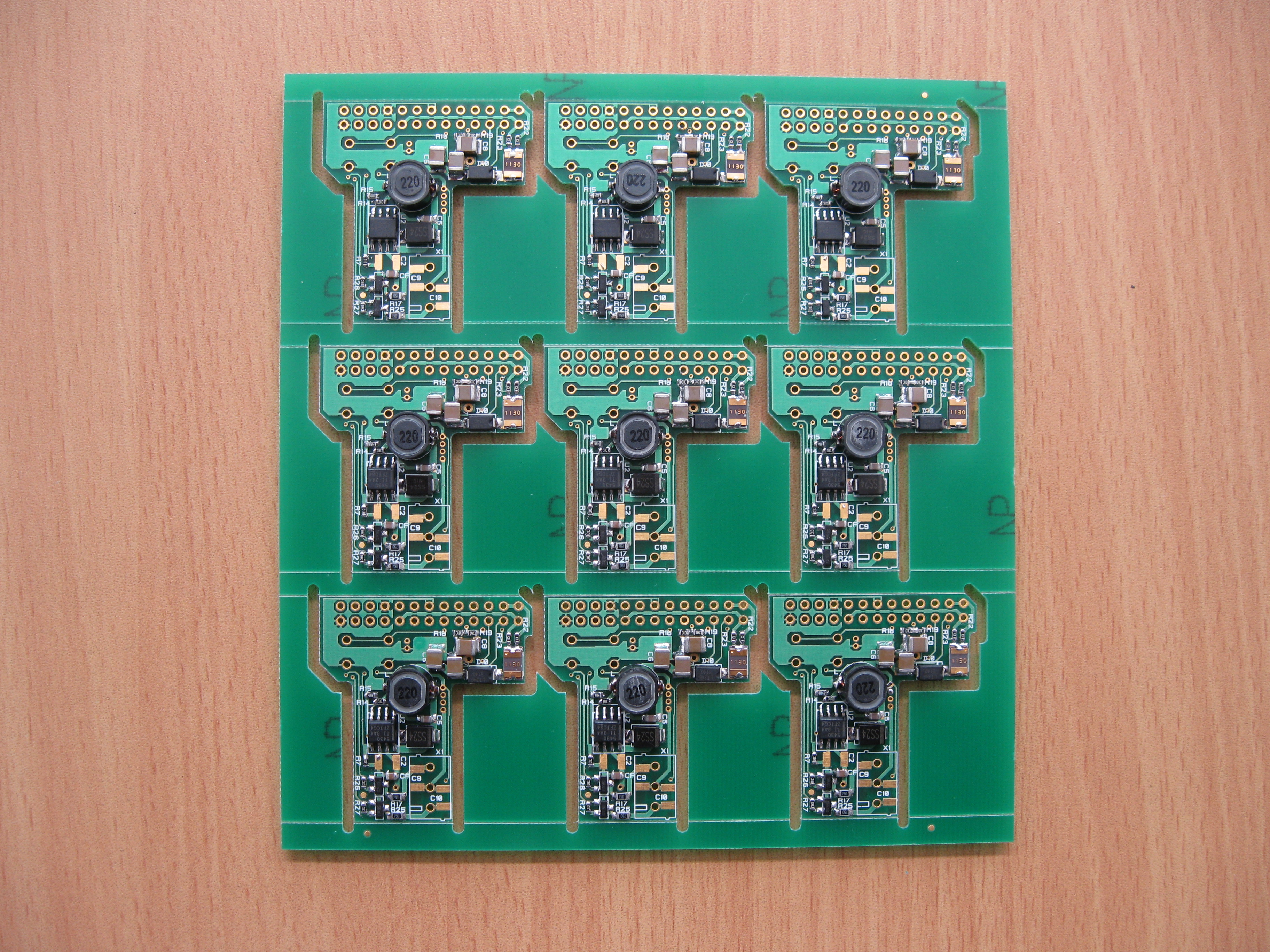
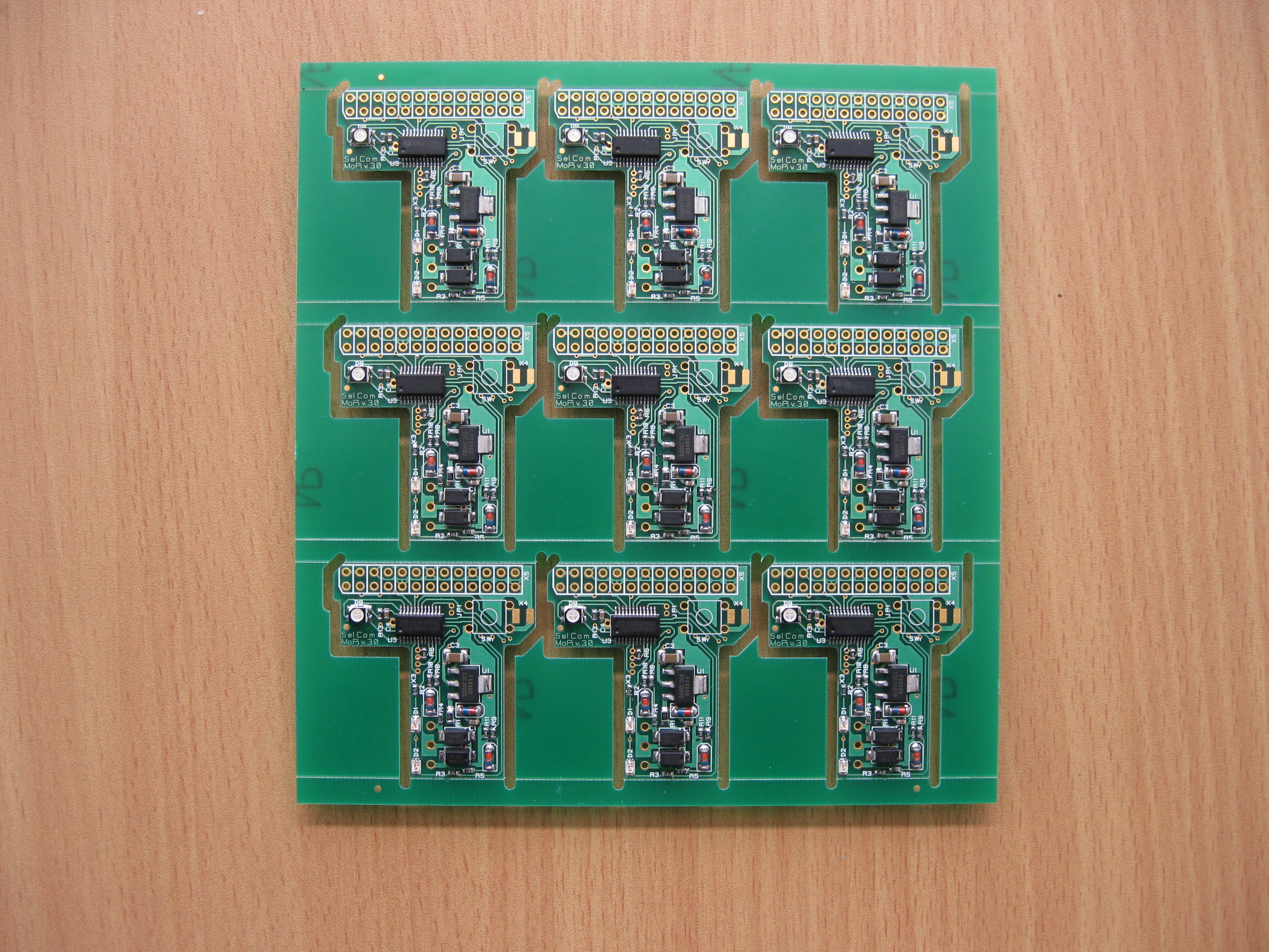
We've now developed four versions (the last of which is being supplied to our Kickstarter backers in June 2014). Here's what version 4 looks like:
|
|
|
|
|
|
|
|
|
|
|
|
|
|
|
|
|
|

Here's what the level 3 revision looked like (without the wiring connector or the GPIO connector or the power switch, which were soldered by hand after these pictures were taken):
Top of the board:
Underneath the board:
The stackable headers (for when MoPi is used in tandem with other add-on boards) take up quite a lot of vertical space in order to provide a set of pass-through pins above the MoPi board. Therefore we offered two versions, one with the stackable header and one with a standard low-profile header.
This is the stackable header that we're using (from Adafruit):

You can see an example here of the low-profile header, on the revision 2 board:
Here's the other side of the second-generation prototype board with some batteries:
The shape of the PCB allows it to fit into the Pibow without blocking the Pi's display output (soon to be used for the Pi Foundation's DSI touch screen). There's space for a pass-through GPIO header so that other add-on boards can share space on the Pi, separate LEDs for overall function and for the two power inputs, and a neat little power switch on the top.
(The good people at Pimoroni are doing a custom lid for their Pibow case to give direct access to MoPi's power switch and stacking header. See it here!)
And here are the first-generation prototype boards:
|
|
|
The software is open source (of course) and available at our Pi-Tronics repository.
The basic functionality was all in place by early 2014; the success of the Kickstarter allowed us to add lots of new features, including:
- Dealing with more rechargeable battery chemistries.
- The internal Pi circuitry can run on 3.3 volts (saving some power loss in the on-board linear regulator — Dave Akerman's balloons use this strategy to increase battery life); MoPi can now be hacked to support 3.3 volt output. :-)
- 2-way communication (on the I2C bus) between MoPi and Pi supports configuration from the Pi.
- Screw terminals, stackable headers, remoting pads and self-resetting fuse.
- Remote power-off and timer-based wake-up added.
The next two sections discusses the overall design of MoPi and then the monitoring and configuration software. Then we give some detail of how it works, and look at system performance and measure how long a Pi can run with various configurations and battery types. We also describe a few of the millions of applications for mobile Pi power. Finally we link to sites selling batteries and some other useful resources.
4.2. The Perfect Battery Pack
What would the perfect Pi battery pack look like? It should be:
Low cost. Dedicated battery supplies like those sold as phone charging devices are great, but when they no longer hold charge the whole unit has to be recycled. Standard commodity batteries and the reusable chargers that serve them are well-established and already present in many households. They're the cheapest and most flexible option.
Flexible. Got a solar panel handy? I want to plug it into the circuitry and have it drive the Pi as long as the sun shines, then let a battery take over when the clouds come. Stuck for power but got an old laptop supply or 12 volt car charger handy? Strip the cables, connect, and power my Pi please! Plugging a bunch of peripherals? I want to be able to drive them all via my battery pack. And etc.
Polite. When you're running your laptop on battery and it runs out of juice it gives you a nice polite warning message or two, and, when the level gets really low, it automagically shuts down the machine. This is important to allow the operating system (e.g. Raspbian Linux on the Pi) to close up any open files and generally tidy the house before power disappears. Just killing the power without warning is risky — sometimes nothing bad happens, but in the worst case you can end up with a machine that won't boot and needs a complete reinstall. So I want my battery pack to signal the Pi when levels are low, so that the Pi can shut itself down cleanly. Good manners are important, after all. :-)
While we're at it, if the battery pack is going to tell the Pi when it is getting low and needs to shut down, why not have an on/off switch into the bargain? The "off" signal triggers clean shutdown, and is very convenient when you're using the Pi in any kind of kiosk or appliance context. Several projects have implemented this type of on/off facility in its own right — e.g. the ATX Pi supply or the PIC controller — it's definitely a useful function to have on board.
Uninterruptible. I don't want to stop work when my battery is low if I've got a charged pack handy (or a different source of power, like a car cigarette lighter socket or the like). So I'd like my battery pack to support hot-swap of a new electricity supply, either a new set of batteries or some other new input.
Eco-friendly. One of the great things about the Pi is its low carbon footprint. The recent ones in my lab are made in Wales, so they haven't travelled half way around the world to reach me. The base system is bare-bones, which encourages reuse of power supplies, monitors, cables and the like. The power consumption is low — particularly for the Model A, which gets by on 300 mA or below (at 5 volts this adds up to around 1.5 watts — contrast that with 50 watts and above for a desktop PC!). There's no spare planet and our resources are definetely finite, so we definitely want to support rechargeable batteries. Preferably not the built-in variety (like a mobile phone) that are hard to recycle.
Communicative. I want to know when the battery is full, when it is starting to get low and when it is critical. I want to be able to get those signals both when logged in to the Pi and visually from the battery pack itself. (Look! Flashing lights!)
Robust. I'm pretty unreliable at the best of times. When crawling through the underbrush with a camera-equiped Pi rig in search of Pine Marten lairs I'm very likely to plug the wrong end of the stick and end up with my foot in my mouth, to coin a mixed metaphor or three. Over-volt and spike protection are definitely requirements.
5. The MoPi Software Suite
This section describes how the MoPi software suite works and how the architecture of MoPi hangs together.
There are four main parts of the puzzle:
- A daemon which runs in the background on the Pi, which is called simbamond (simbamon daemon, or SImple BAttery MONnitor daemon). It is available as a package for Raspbian, and installing it pulls in all MoPi software.
- An interface that communicates with the MoPi hardware over the I2C protocol. This interface is wrapped up as a Python API.
- A command-line tool that uses the Python API and provides a language-neutral portable method for talking to the board from the Pi.
- A configuration user interface that simplifies the process of setting up MoPi to deal with different types and numbers of batteries, and other types of power supply.
All of the code for these components is available on GitHub.
The rest of this section discusses each of the main elements in turn, describes how to check up on the beast as it runs, and finishes up with more detail of the implementation of the daemon.
5.1. simbamond, the simbamon daemon
When the Pi (or any other Linux system) boots, several system services are started that will run continuously until the machine is shut down again. These services are called daemons, of which simbamon is one. The first point of entry, used by the operating system to start, stop, etc., is an init (think initialisation) script: /etc/init.d/simbamond. This script (which you can think of as a wrapper for management) calls another script to do the real work: /usr/sbin/simbamon.
One of key features of MoPi is that it supports many different types of batteries and many other types of power supply (from solar panels to elastic bands!). Coping with the requirements of all these monsters needs a huge wodge of configuration data, which (following Debian Linux convention) lives in /etc/default/ in a file (again, confusingly) called simbamond.10
Together these three script files make up a new system service that polls the MoPi hardware every couple of seconds and shouts loudly when an electron shortage appears on the horizon. If no one is listening and the shortage gets acute, the daemon tells the Pi to take a rest and issues the shutdown command.
There is more detail below.
5.2. The Python API
How do we talk to the hardware? From MoPi version 3 onwards we shifted away from using the Pi's general-purpose GPIO pins (using a tool called WiringPi). This worked well, but it used a pin for each bit of data that we wanted to ship between the board and the Pi. As time went on we found more and more data that we needed to share (and we also came across other add-on boards that use lots of GPIO pins — e.g. AirPi).
Luckily the Pi also hosts several other inter-board communication options, including the I2C protocol, which uses only two pins, can talk to multiple devices over the same two wires, and allows transfer of much larger amounts of data.
There are two ways to talk over I2C from the Pi: a set of command-line tools written in C, and a Python module. Both work, but the Python version seems to have had more attention from Pi users and developers, and even has support for multi-byte reads. So we've implemented an API for MoPi in Python11, which now lives in a file called mopiapi.py. For Python programmers this code provides a natural and efficient method of including MoPi facilities in their programs. For example, writing a system tray applet...
5.3. MoPi from the Command Line
The observant amongst you may have noticed that simbamon is not written in Python12 — how does the daemon talk to the board when the API is in Python? That's where mopcli comes in, which is a command-line interface to the Python API. This script provides convenient methods for the daemon to use, or for Pi users to query and configure the board, or for our configuration utility — which by amazing coincidence is described next.
To see what the beast can do, ask it for help by typing sudo mopicli -h; you'll get something like this:
Usage: mopicli [-h] [options]
This tool is for interfacing with the MoPi battery power add-on
  board for the Raspberry Pi. (http://pi.gate.ac.uk)
Package Version 4.0
Version 0.5, API 0.3

Miscellaneous:
  -i x	I2C bus
    Where x is the I2C bus that connects the MoPi to the Raspberry Pi. If ths
    flag is not set, the default bus of 1 is used, based on board revision.
  -fv	Firmware version
  -sn	Serial number
  -h	Display this message
  -e	Read everything possible from the MoPi
  -nl	No labels on output

Status:
  -s	MoPi status word
  -sv	Verbose status
  -v	Current source voltage in mV
  -v1	Source #1 voltage in mV
  -v2	Source #2 voltage in mV

Read configuration options:
  -rc	Combined source #1/#2 conf
  -rc1	Source #1 conf
  -rc2	Source #2 conf
  -ron	Power on delay
  -rsd	Shutdown delay

Write configuration options:
  -wc t mV mV mV mV	Combined source #1/#2 conf
  -wc1 t mV mV mV mV	Source #1 conf
  -wc2 t mV mV mV mV	Source #2 conf
    Where t (type) is 1 for rechargeable batteries, 2 for non-rechargeable
    batteries, 3 for PSU / DC adapter, and the four mV settings are the
    mmaximum, good, low, and critical voltage levels.
  -won seconds		Power on timer in seconds
    This timer counts down from the moment the MoPi is powered off and turns it
    back on when reaching zero.
  -wsd seconds		Shutdown timer in seconds
    This timer counts down from the moment it is set and powers off the MoPi
    when reaching zero.

All options may be used simultaneously. When doing so, they execute in the
  order they are listed in in this help message. However, only one of each may
  be used.
As easy as pie.
5.4. Configuring Your Power Supplies
Not quite so easy is choosing the correct voltage settings for different battery chemistries and different combinations of cells (not to mention other types of power supply). In each case MoPi needs to know:
- What is the approximate voltage that the battery will supply when fully charged?
- What is the point at which we're getting low on charge? (And therefore may expect to run out of juice within a few minutes or so.)
- what is the minimum safe discharge voltage? (Just above the critical deep discharge level of the batteries.)
The mid-point between the first two voltages is is the conventional definition of what a good level of charge is, so that's where we swap between lighting up our RGB led in blue and lighting it in green. When we reach the low charge point we turn the LED red, and when we reach the minimum safe discharge voltage (or the minimum safe operating voltage of our micro-controller at 6.2V if that is higher) then we initiate shutdown.
Let's look at each of these values in more detail:
- Fully-charged voltage. This is equal to the fully-charged voltage of each cell in the battery pack multiplied by the number of cells. Like most things with batteries, it varies according to battery chemistry — e.g. an Alkaline cell generates 1.5V; a NiMH 1.2V; a LiIon 3.7V.
- The low charge level. When you record the voltage delivered by a battery over time, most of the curves exhibit a knee shape. Before the knee voltage drop is reasonably slow; after the knee if drops much more sharply. We need to try and warn the user around the knee point, so that they have enough time to replace the battery before it drains completely, but not so much time that there is still lots of usable charge left.
- Minimum safe discharge voltage. This applies to all rechargeable batteries. If we discharge below this level, then the capacity to recharge will be impared. This makes it a very important factor in battery life for the long term, and one which we've done a lot of work to model and adapt to. (Ever wondered why the rechargeables that you put in your alarm clock or torch lasted such a short time? Most devices have no way of knowing about the minimum discharge level for the particular chemistry you're using!)
- Minimum safe operating level. MoPi uses a sophisticated microcontroller to analyse battery behaviour, control its LEDs and deliver data to the software suite running on the Pi. If the supply voltage to MoPi falls below a certain level (around 6.2V) then the microcontroller may terminate, or even start to behave unpredictably. It is very important to trap rapid voltage drop before it reaches this point.
To deal with all these considerations, the current version of the software stores these values:
        TYPE         CELL/FULL  MIN

  1     non-battery     9.0     6.2
  2     NiMH            1.2     0.95
  3     Alkaline        1.5     0.8
  4     Lead Acid       2.0     1.58
  5     Lithium Ion     3.7     3.0
  6     LiPo            4.2     3.0
  7     NiCd            1.2     1.1
When we know what chemistry we're dealing with, and how many cells, we can then make good guesses about where the four levels above should fall. But how do we know what the chemistry is? Two ways:
- We have two built-in defaults, one for 8 NiMH cells (which is the battery pack that we're supplying to backers who requested one), and one for 8 Alkaline non-rechargeables. The latter is what MoPi will assume when running out of the box; the former is activated by removing the on-board jumper provided for the purpose13.
- You tell us! To this end we have developed a configuration UI on the Pi, which is the last piece in our four part software puzzle.
The configuration UI uses the same tools as the Raspberry Pi's utility (raspi-config), so it should be simple and familiar, and it can be used over all types of connections (including remote login with ssh). Here's a screenshot or three:

The main entry screen.
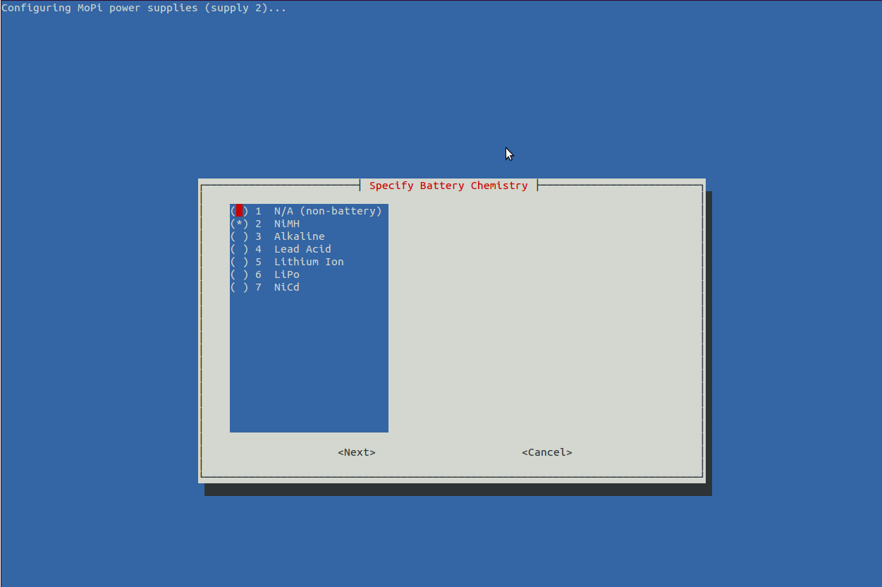
Configuring one of the power supplies, battery chemistry.
Getting status data (there's lots more in the newest version!).
Dive into the source code here.
And now you know more about batteries than you ever wanted to — just like me!
5.5. Monitoring
As you can imagine, figuring out how all this stuff is working and identifying bugs and incorrect behaviour is quite a challenge. Luckily we have some great tools to help us, one of which is Monit. This little gem is itself a daemon, and it has facilities for one thousand and one different types of monitoring task. You can listen to your webserver and restart it if it fails, or check the general load of the machine you're running on, or — in our case — check that the simbamon service is running, and if not start it up.
To use it, all we need to do is sudo apt-get install monit in the usual way, then edit /etc/monit/monitrc. This is the config we're using to monitor simbamon on one of our test rigs:
###############################################################################
# monit config for simbamond, from /etc/monit/monitrc #########################

# monitoring UI (serve on port 8888 and allow connections from one IP address)
set httpd port 8888 and
  allow 192.168.1.111

# general system status
check system mopi-15
  if loadavg (1min) > 4 then alert
  if loadavg (5min) > 2 then alert
  if memory usage > 75% then alert
  if swap usage > 25% then alert
  if cpu usage (user) > 70% then alert
  if cpu usage (system) > 30% then alert
  if cpu usage (wait) > 20% then alert

# monitor simbamond
check process simbamond with pidfile /var/run/simbamond.pid
  start program = "/usr/sbin/service simbamond start" with timeout 60 seconds
  stop program  = "/usr/sbin/service simbamond stop"
  restart program = "/usr/sbin/service simbamond restart" with timeout 60 seconds
  if cpu > 60% for 2 cycles then alert
  if cpu > 80% for 5 cycles then restart
  if totalmem > 200.0 MB for 5 cycles then restart
  if children > 250 then restart
  if loadavg(5min) greater than 10 for 8 cycles then stop
  if 3 restarts within 5 cycles then timeout
  group mopi
###############################################################################
You can then see what's going on by either or both of
- cat /var/log/monit.log (| grep simbamon is also useful)
- pointing your browser at http://my-pi-ip-address:8888 (if you need to find your IP address various methods are discussed here)
This is great for keeping check on things during load testing (particularly heavy loads which have a tendency to cause odd corner case bugs to trigger), but it is also a great tool for maximising service availability — the configuration code above will restart simbamon within a couple of minutes should it ever crash, for example.
5.6. simbamon: a simple battery monitor
5.6.1. Design Notes
There are a variety of ways that laptops communicate with and control their batteries, including the Smart Battery specification (which often uses SMBus, a variant of the I2C interface that the Pi supports). In Linux the resultant data feed is then modelled using a power management abstraction (of which ACPI is the most recent) and manipulated using a driver specific to the battery in use.
Sounds like a good idea? Yes, in the abstract, but implementing a new driver is quite a job — here's one that runs to 1200 lines of C code, for example. It is also not clear how to do this when we have the ability to plug in batteries of different types, which is something we really wanted to support.
What to do?
If in doubt, take the simple option. All Linux systems share the system service or daemon concept. A system-level process which gets run during startup. It is quite easy to implement a battery monitor daemon that listens on the Pi's I2C bus for level changes signalled by the MoPi microcontroller board. The daemon then makes entries in the standard system logs as a simple way to share data with other subsystems, and can be configured to send a warning message to all users if levels are low. Best of all, the daemon can easily shut down the Pi cleanly before the regulator voltage gets too low for reliable operation.
5.6.2. Implementation
This section gives more detail of the implementation of the simbamon battery monitoring daemon. It is designed for the MoPi boards, but should be quite easily reusable for other battery power projects. simbamon is an open source Linux daemon for:
- Monitoring battery levels (for us this is done via the mopicli command).
- Sending warning messages to the user if the battery is low.
- Shutting down cleanly at critical battery levels.
- Managing a power supply on/off switch.
- Writing relevant data to the system logs.
You can find the source code on GitHub. The core of the daemon is defined in three files:
- /etc/init.d/simbamond — an interface to the init subsystem that Linux uses to manage daemons (amongst other things)
- /usr/sbin/simbamon — the daemon itself
- /etc/default/simbamond — configuration data
The first of these, simbamond, is used by the operating system to start and stop simbamon at boot or shutdown time, and can be used to control simbamon manually when required. For example this command will stop the daemon:
sudo service simbamond stopThe configuration file, (also) simbamond, defines how simbamon will take action. Of primary interest is the last few lines, which specifies the battery configuration in CLI format. There's some generic stuff at the top too about monitoring frequency and stuff, it's pretty well explained in the file.
####################################################################
# local config - DON'T EDIT THIS LINE!
# -wc 1 11200 10000 8800 8000
# end of local config - DON'T EDIT THIS LINE EITHER!
The MoPi microcontroller supplies these states via the Raspberry Pi's I2C bus (and also sets on-board indicator LEDs accordingly). The core of simbamon, a shell script that lives in /usr/sbin/simbamon, implements an infinite loop that checks the levels being reported every few seconds and takes any necessary action. The wall command is used to send messages to any user currently logged in.
Here's a condensed version of the main loop (error checking, debug logging and other details omitted):
while :
do
  # loop indices
  i=$(( ${i} + 1 )); j=$(( ${j} + 1 ))

  # get MoPi status
  MOPI_STATUS="`mopicli -nl -s`"

  # action states (shutdown or warn)
  if s_forced_shutdown "$MOPI_STATUS"
  then
    wall <<< "${NAME}: power off requested: shutting down now!!!"
    logger "${NAME}: shutting down (POWER_OFF; ${MOPI_STATUS})"
    eval "$SHUTDOWN"
  elif s_bat_critical "$MOPI_STATUS"
  then
    wall <<< "${NAME}: battery empty: shutting down now!!!"
    logger "${NAME}: shutting down (BAT_SHUTDOWN; ${MOPI_STATUS})"
    eval "$SHUTDOWN"
  elif s_bat_low "$MOPI_STATUS"
  then
    if [ $PREV_WARNING -eq 0 -o $(( $i - $PREV_WARNING )) -ge $WAIT_LOOPS ]
    then
      PREV_WARNING=$i
      wall <<< "${NAME}: ${LMESS} is low! connect new battery or shut down"
      logger "${NAME}: BAT_WARNING (${MOPI_STATUS})"
    fi
  fi

  # routine log messages
  [ "$DEBUG" = on -o ${j} -eq ${LOG_INTERVAL} ] && \
    logger "${NAME}: ${LMESS} is ${MOPI_STATUS} at `pdate` (i=${i})" && j=0

  # take a break
  sleep ${MONITOR_FREQUENCY}
done &
Here is the
current version of the code.
5.6.3. Installing simbamon
The Raspbian maintainers have been kind enough to include simbamon in their repository, so you can just do this (as noted above):
sudo apt-get install simbamondOur software is also available from an Ubuntu Personal Package Archive (PPA). (The Ubuntu infrastructure doesn't currently work for binary Pi packages, but simbamon and the rest of the MoPi suite is implemented in script (shell and Python), so we're ok in this case.)14 To install from this archive:
1. Add this line to /etc/apt/sources.list:
deb http://ppa.launchpad.net/hamish-dcs/pi-gate/ubuntu precise mainYou can use a text editor (e.g. nano) to do this, or paste this one-liner into a terminal prompt:
echo deb http://ppa.launchpad.net/hamish-dcs/pi-gate/ubuntu precise main |sudo tee -a /etc/apt/sources.list2. Import the GPG encryption key from Ubuntu so that the Pi can verify the package's validity:
sudo apt-key adv --recv-keys --keyserver keyserver.ubuntu.com --recv-key 6C12C1CF3. Update your list of available packages (this may take a couple of minutes):
sudo apt-get update4. Install the package:
sudo apt-get install simbamond(You may ignore errors refering to module loading here — see below for details.)
And that's it!
Note: the above gets you the most recent stable release; if you want to live on the edge, you can get more recent experimental builds by adding the snapshot PPA to your sources list, e.g.:
echo deb http://ppa.launchpad.net/hamish-dcs/pi-gate-snapshots/ubuntu precise main |sudo tee -a /etc/apt/sources.list
6. How it Works: the Hardware
The MoPi circuitry consists of two parts: a single-chip microcontroller and a five volt switching mode regulator. The microcontroller (with embedded firmware) implements all the functions related to voltage level monitoring, level signalling (via the LEDs and the GPIO interface), and on/off switching of the +5V supply to the Pi. Battery voltage levels are measured using the built-in microcontroller ADC15.
The schematic looks like this:
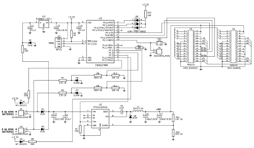
Two yellow (or amber) LEDs are positioned next to the twin power pack inputs (screw terminals), and indicate their status (blinking when either voltage is critically low). The overall voltage level of both power inputs is indicated by one RGB (three colour) LED and is also sent to the Raspberry Pi over the I2C bus. The 5 volts to the Pi is generated by a highly efficient switch mode voltage stabiliser, driven by the microcontroller. An open source daemon running on the Pi listens to the I2C signal, informs the user of low battery levels and shuts the Pi down cleanly when levels are critically low (or when the power switch is pressed, or a delayed shutdown counter expires).
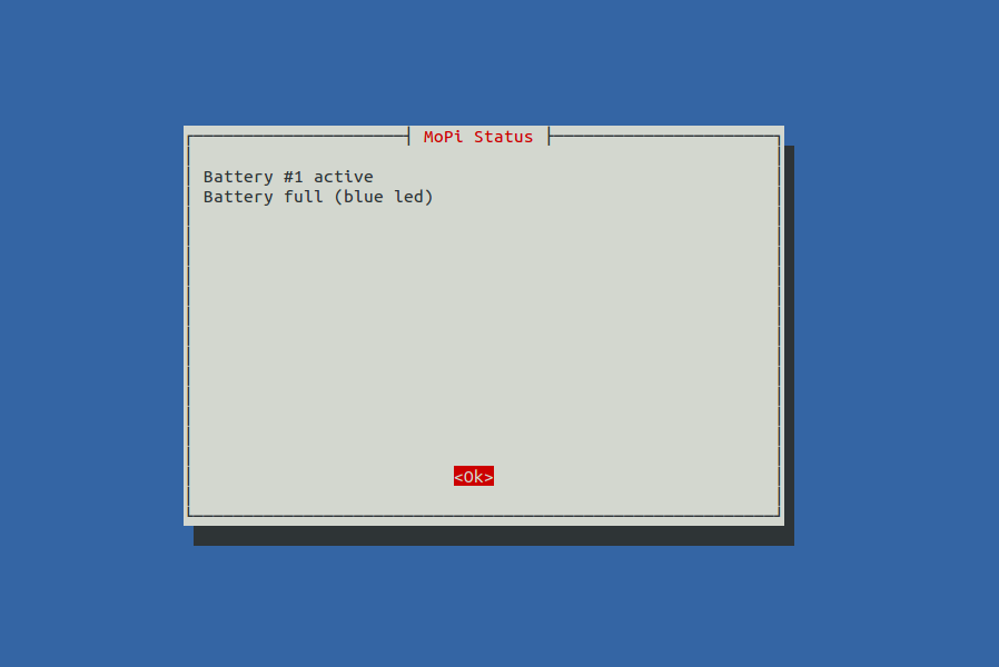
To start the 5V generator the power button should be pressed and held for 3 seconds. The microcontroller checks the voltage level of the attached battery packs under load and if it is above the defined critical battery threshold, it switches the stabiliser on to generate 5V for the Pi. The yellow LED for the connected power input lights up, and the RGB LED lights up blue when the battery pack is fully charged (or green if the voltage level is within the acceptable operating range). The current voltage level is also accessible to the simbamon daemon on the Pi via I2C16. During operation, the microcontroller continuously monitors the voltage level, and when it falls beneath a low battery level that it believes leaves only a few minutes of operational time, it switches the RGB LED to red. Simultaneously the yellow LED for the low battery starts flashing, indicating that the pack needs replacement.
At the same time the LED turns red and the yellow LED starts flashing, simbamon (the monitoring daemon on the Pi) gets a low battery flag and informs the user that they should either plug in another supply or shut down (again by pressing the power button for 3 seconds). If nothing changes and the battery continues to discharge down to a critical level, then the RGB LED starts flashing red and MoPi forces a shutdown. The user can then remove the old battery pack for charging.17
Behaviour has to be adjusted for multiple battery chemistries; this is done within the microcontroller firmware and can be configured from the Pi. MoPi has two default discharging profiles pre-programmed — one for NiMH rechargeable batteries and one for ordinary Alkaline batteries. Out of the box the Alkaline profile is active; to choose the NiMH profile, remove the small jumper located on the under side of the board. The jumper applies to both power inputs. The state of the jumper can be overridden via configuration from the Pi, separately for each one of the power inputs. Note:
- The jumper is tiny, and easy to lose. If you need to remove it, do so, but it is then best to replace it, but on only one of the pins.
- When supplying MoPi with NiMH rechargeables we remove the jumper to activate the relevant default profile. (And replace it on only one pin.)
MoPi can be used as a UPS (Uninterruptible Power Supply) in two ways. If the Pi is powered over its 5V micro-USB socket and that power drops while MoPi is active, the supply fails over transparently, allowing the Pi to continue work uninterruped. Note though that if the battery supply drops to critical level simbamon will shut the Pi down. We're working on various circuits that work around this issue. Alternatively an AC adapter can be plugged into one power input on the MoPi and batteries into the other. Neither option gets around charging the batteries. Like we said, we're working on it.
7. Testing
7.1. The Longer-Lasting Snack
So, how long will the batteries last?
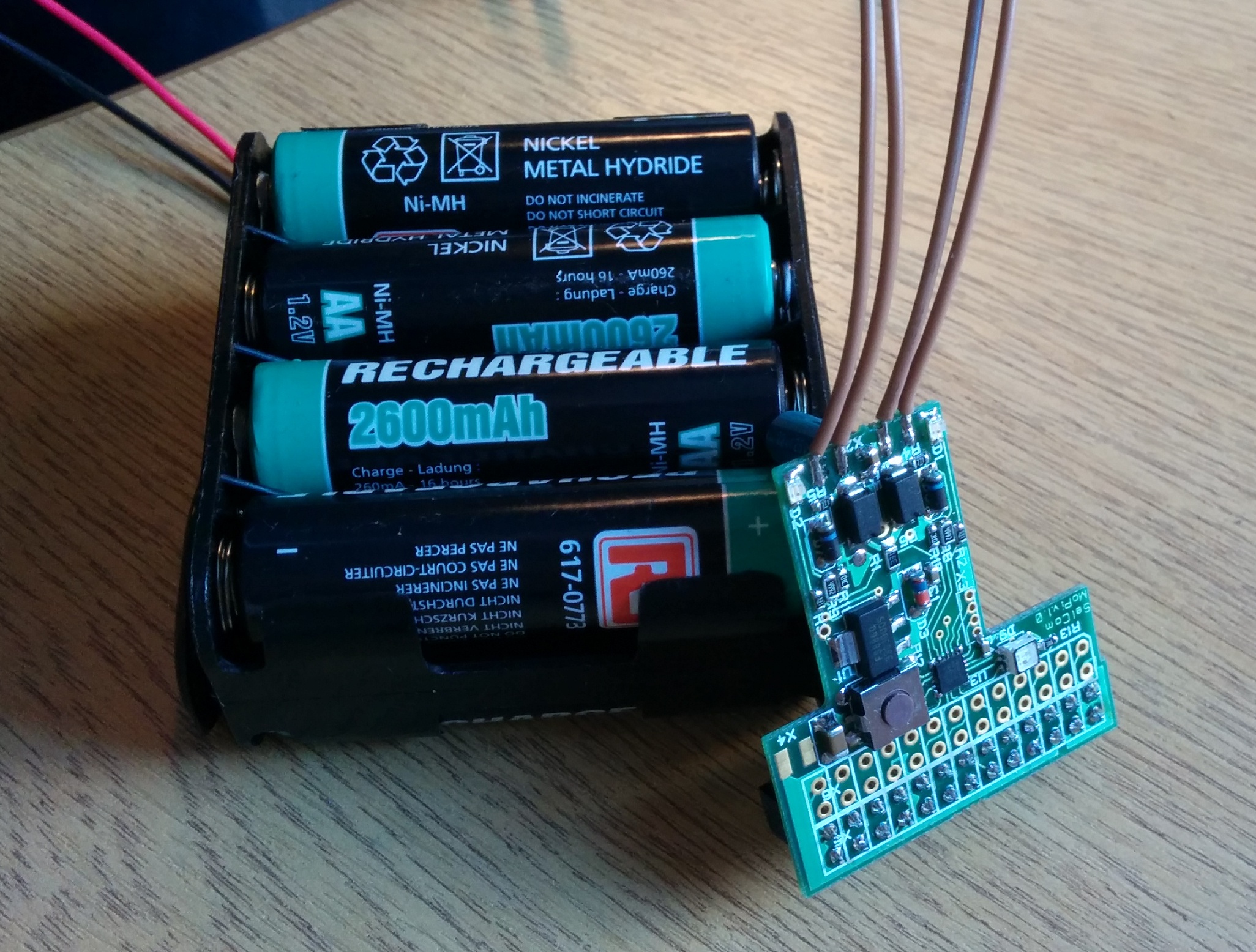
My first test was a Model B Pi with almost no load (USB keyboard and mouse; monitor attached over HDMI but switched off after starting the test; no network or other peripherals). Using eight rechargeable Duracell AA NiMH 2400 mAh batteries (like these ones) the Pi ran for 9 hours 31 minutes. Not bad! Especially when you consider that the MoPi regulator supports hot-swap of new charged packs — this looks very viable for mobile Pi applications of all shapes and sizes.
For comparison I set up the same rig with a USB battery pack from RS (this one, a 5200 mAh Lithium polymer model). The results were remarkably similar, with the RS pack lasting for 9 hours and 21 minutes.
Since then we've conducted 101 different tests. There are three key factors in battery life: 1. Model A vs. Model B; 2. the peripherals; 3. Activity. To summarise:
- You can expect a Model A in some cases to get more than double the battery life of a Model B.
- What you connect to the Pi makes a huge difference. For example, WiFi is a power hog. It will more than halve the battery life of a Model A. It will be even worse on a Model B. A keyboard or accelerometer in contrast, is cheap. XLoBorg won't reduce your running time by much in comparison.
- How much you're doing impacts things. If the Pi is effectively idle, just running wit the odd SD card read/write you get the best battery life. As you use the CPU more battery life goes down.
You can also connect two battery packs to MoPi and get double the running time.
7.2. Battery life
We've tried using the MoPi in a few different ways, with different combinations of Pis, Peripherals, Batteries, and Tasks to find out how long the batteries can last. So far we've tried the Model A with some different USB devices and with different batteries. We've also tried the Model B with different batteries. Let's have a look at some of the results...
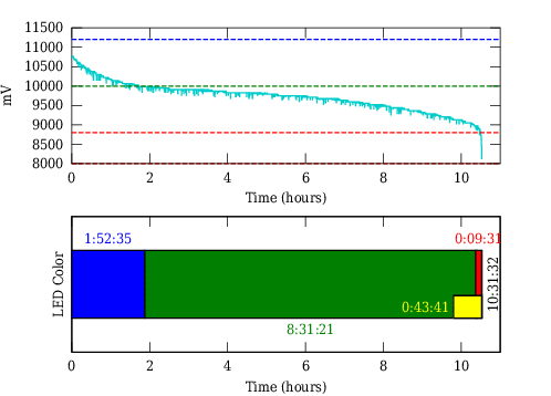
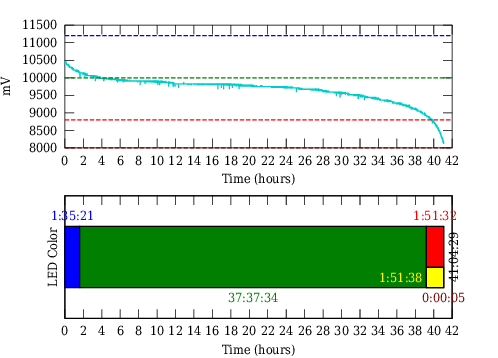
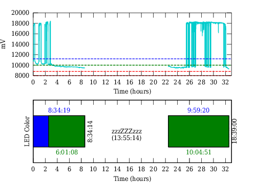
A Model A with two sets of 8 fresh RS NiMH 2600 mAH batteries (16 total):
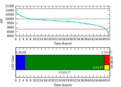
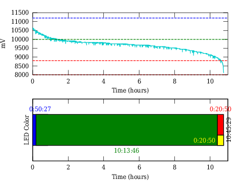
First a quick explanation of the plot. The top half of the figure shows the voltage levels. The aqua line is the voltage level of the active power source. The batteries pretty much drain perfectly in parallel so it's effectively really the voltage level of each battery pack in this case. (If there's only one pack attached it's the voltage level of that pack.) The dashed blue, green, red, and crimson lines are the voltage levels that affect LED color. Above the green line the LED is blue. Below the green line it's green, until the red line where it's red. Below the crimson line the LED is flashing red and the MoPi is about to shutdown.
The bottom half of the figure shows what we're most interested... time. Specifically the colored bar shows how long the MoPi was showing each color on the RGB status LED. The yellow bit of the bar corresponds to how long the input status LED was flashing. So in this case we had 5 hours 30 minutes of blue LED. 43 hours 8 minutes of green LED. 2 hours 44 minutes of red LED. A whopping total of 50 hours 38 minutes. Of a Pi. Turned on. Running on AA batteries.
This of course is pretty much the ideal scenario. The Raspberry Pi was just sitting there, nothing attached, not doing anything but logging voltage once every 5 seconds. The batteries were brand new. The little dips in the aqua line probably correspond to the SD card being written to or some service (like cron) on the Pi activating briefly before going back to being an idle process.
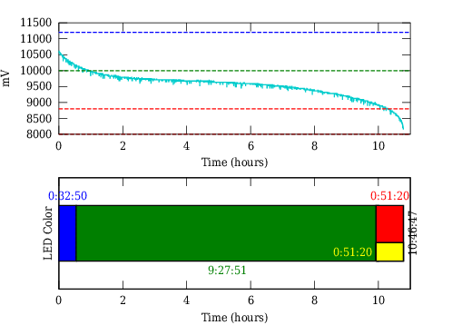
Let's look at a less ideal scenario. Two sets of the same batteries connected
to a Model A, but this time they're old. They've been through at least a dozen
or two recharge cycles. There's USB Ethernet18 with an active SSH connection. What happens now?
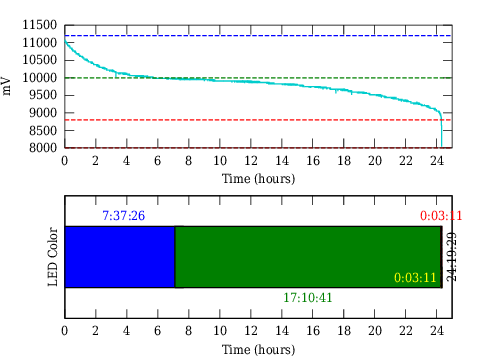
Oh my! Battery life is now down to half of what it was! Only 24 hours 19 minutes in this case. The Ethernet and SSH connection has definetely used some power. How much it's hard to tell, but this is definetely a more realistic usage scenario.
The shape of the discharge curve is also interesting to see. Voltage drops much more sharply, giving less warning that the batteries are low. This is almost certainly a result of the age of the batteries.
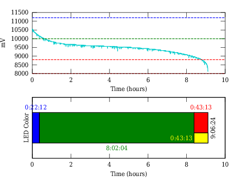
Now how about just 8 old batteries:

12 hours! It's pretty much bang on half the uptime for half the batteries.
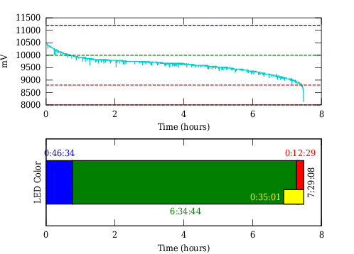
What about WiFi now? Same deal, Model A, 8 old batteries and an active SSH
connection:
10 hours 30 minutes. We've paid a 1:30 penalty for wireless flexibility. That's roughly 12% drop in battery life. With two battery packs we'd loose around 3 hours of battery life.
What about the Model B? Let's go back to full idle and 8 fresh batteries:
10 hours 46 minutes. Wait, what? With a Model A we'd expect around 24 hours for 8 fresh batteries. What's different then between the Model A and the Model B? There are at least two things: 512 MB of RAM vs 256 MB of RAM; and the Model B has the on board Ethernet (which includes a USB hub for the two USB ports that the Model B sports). I'm inclined to blame the USB chip here. According to the datasheet it has a pretty high current draw at 3.3V, which needs to go through the very ineffecient linear regulator on the Model B, further sucking power.
On a side note we can confirm these batteries are fresh by the shape of the dishcarge curve. That sharp drop off is missing.
Let's connect the Ethernet on the Model B, but still leave off an active
connection:
Ouch. We've lost another hour and a half. Simply by connecting the Ethernet, which further activates the USB chip and lights up those LEDs and has the system ready to respond to incoming packets.
Let's see what happens with activity and old batteries now:
Down to 7 hours 39 minutes. That's another hour and a half or so. Based on the information about power consumption available, that still looks like it's mostly due to the Ethernet rather than the age of the batteries. Clearly the way to go is to use a Model A. Anything to get away from the USB chip.
7.2.1. Battery life under load
So far the testing presented has been essentially an idle system (just logging) or a system under light load (active ssh). The next set of testing cranked up CPU usage to look in more detail at how that impacted battery life. The first question is how to achieve CPU load?
Overclockers, people who crank up their CPU speed, often ask the same question. In their case though, they're not looking to look into battery life, but instead they want to check that their system remains stable and won't crash even at higher speeds. They call this "stress testing", which is really just essentially creating CPU load. A popular method of stress testing a CPU is to use Prime95.
Prime95 is a program that verifies known prime numbers are indeed prime as calculated. Often when a CPU is under extreme conditions, the calculations start to come out incorrect, and this tells an overclocker to reduce CPU speed to increase stability. This bit isn't so interesting as we're not really overclocking the Pi (although it is possible). The idea though of calculating prime numbers to generate CPU load is what we're after.
A few years ago I played around with testing prime numbers in C++. I rewrote that program to be something suitable for applying CPU load to the Pi and put it on GitHub.
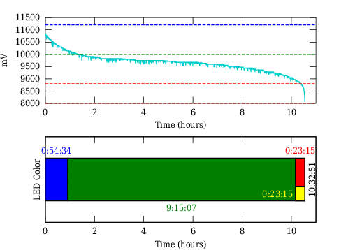
So! Our first test setup now looks like this. A Model A with 16 AAs and CPU
load applied in the form of our prime number testing program:
An uptime of around 41 hours. That's a drop of around 9 hours. However, there are actually two things happening in this test. There's CPU load yes, but also the batteries were charged a few days before actually being used. As a result the start voltage is a little bit lower: 10.4 V as opposed to 10.8 V. Shelf discharge will account for some loss of uptime. Here it's probably around 45 minutes, but this only gets worse with older batteries.
I'll perform this test again later with more freshly charged batteries, but there's an important lesson here. We've said it before and we'll say it again. Battery life is variable. It's not just how you're using your Pi, or what's connected, but also the batteries themselves can affect how long it runs for. The more absolutely consistent you can get your setup the more predictable battery life will be, but it's a good idea to have a plan for when the batteries run low. That's why the MoPi can tell the Pi to shutdown.
But what about the Model B? Yes, we tested that too. 8 AAs, Ethernet, and
active SSH displaying our prime number results:
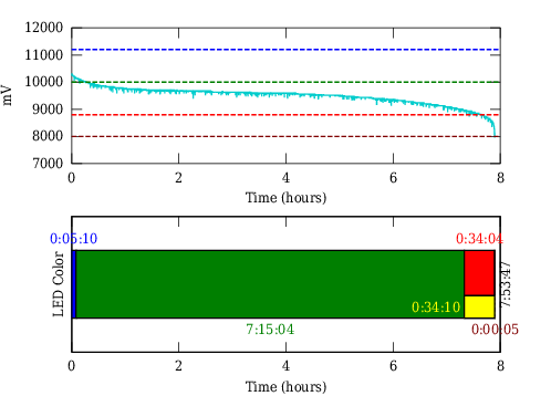
Just under 8 hours with CPU load and Ethernet... compared to 9 hours without CPU load? More time (1.5 hours) is lost simply by connecting the Ethernet than by using the CPU. This says two things. The first, which I've already said, is that the Ethernet is extremely power hungry on the Model B. The second is that really, the CPU of the Pi is pretty energy efficient.
Food for thought. In 8 hours, the Model B managed to check if numbers were prime from 1 up to 690k. My Core i5 desktop did the same check in 6 and a half minutes...
7.2.2. What the sun says
Solar power! We've tried two setups. A low power setup using old panels, and a setup using brand new quite beefy panels. Needless to say we've had more luck with the latter, but the former is interesting too...
Way back in 2002 I tried powering my Z scale model trains with solar panels to some small success. Since then I've held onto the eighteen 5 V/30 mA Panasonic BP-376634 panels I got then, which I try on different projects every now and then. I sucessfully charged a Nokia. I couldn't power a Model B when it was new. But mostly they sit in a drawer. Now though I have a Model A, which I've proved to myself has a much lower energy requirement so I thought I'd try them out yet again.
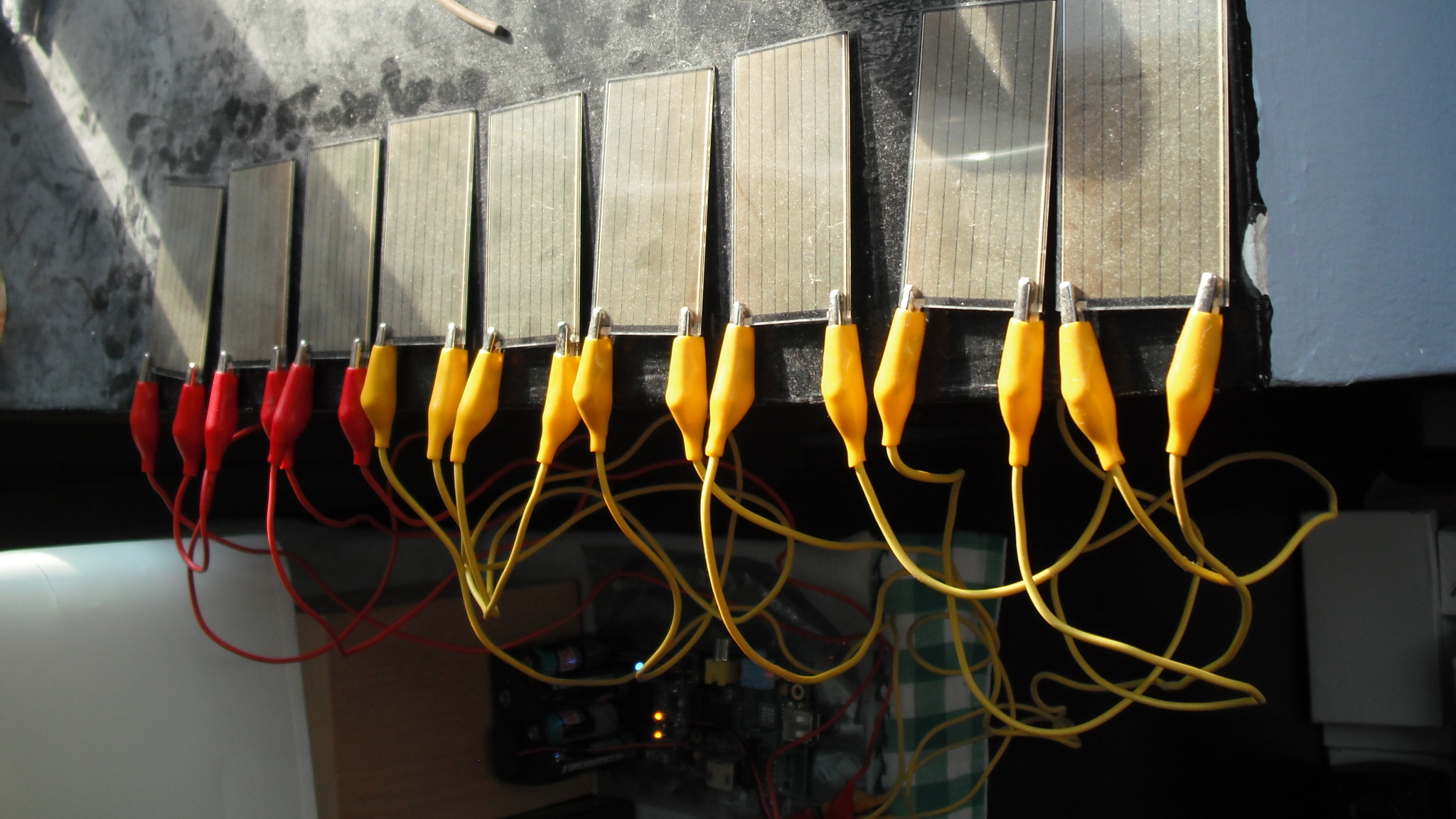
Even though I have eighteen of the panels, my shelf space is limited, some are damanaged, and the aligator clips I use for connecting them are also damaged. It was practical to setup 9, which I put into three sets of three panels for 15 V and 90 mA. While this is probably less than the requirements of the Model A, I figured they might supplement the batteries some and increase how long I could run on a single pack. Which to be fair, they did...
After configuring the input on the MoPi to non-battery source using the
mopi command, a Model A with 8 older AAs and Wi-fi does this:
10 and a half hours, which agrees with the time above. Now with the panels:
10 hours, and 45 minutes! A whole extra 15 minutes! To be fair as well, these batteries probably sat a bit after charging before I used them for this test, so it does seem to help out some, just don't count on it. I suspect using 10 panels to up the voltage (getting 20 V) would have helped a bit as well.
In any event, I know we can do better. See below the outside of our workshop:

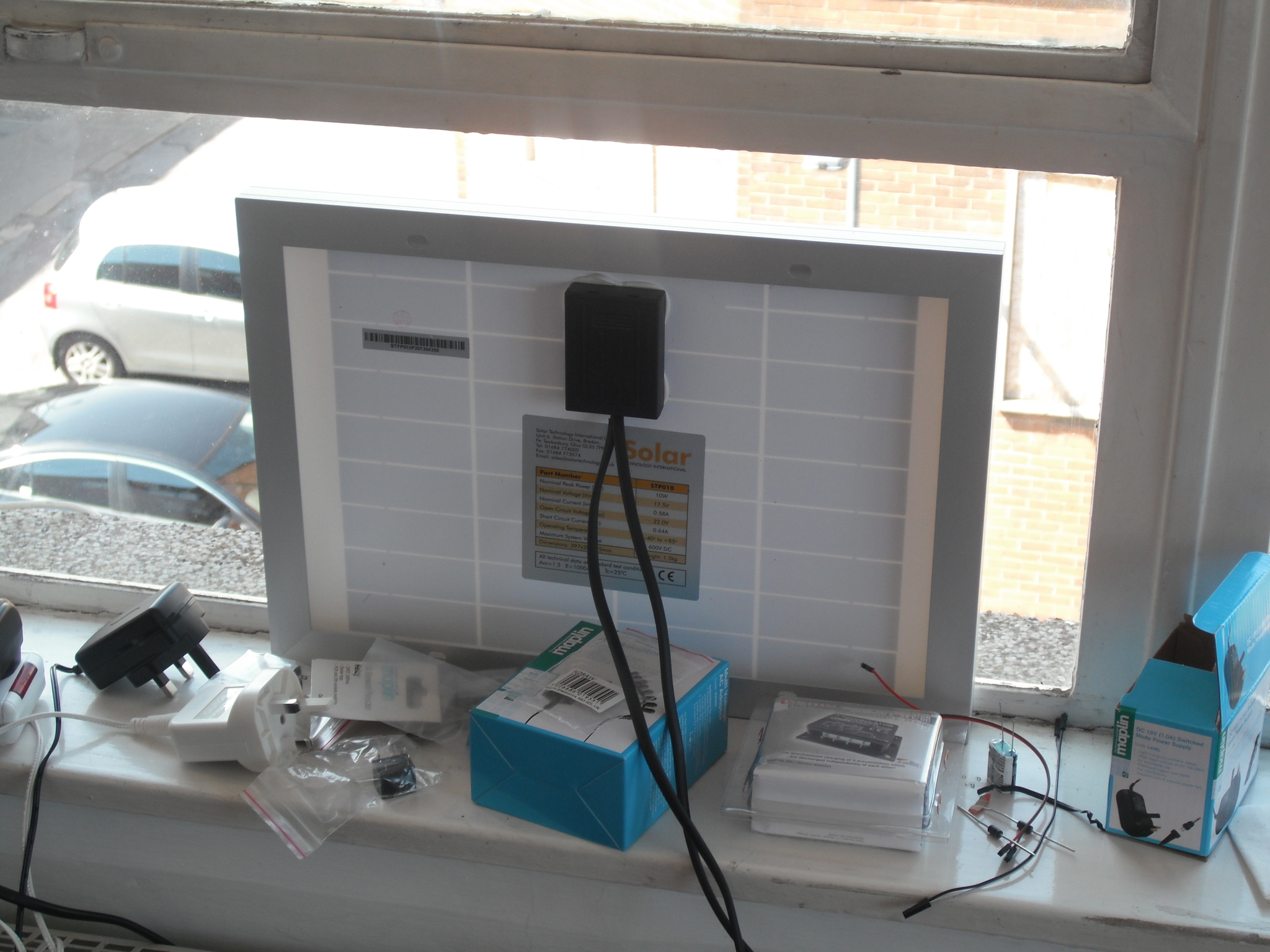
The eyes of that smile are made up of Maplin 10 W panels, rated at 17.5 V or 580 mA. And we have two of them. (We also live in Britain where it's not particularly sunny. That's why we have two of them.) They're connected in parallel to one of the inputs of a MoPi powering a Model B. (You can also see the Pi is connected to Ethernet — this is so that it keeps the time...)
I've also done something clever. The Pi in this case is configured to shutdown nicely around 8 PM. Before this though the MoPi's power-on timer is set for 14 hours, so that the Pi will turn on at 10 AM. This means the Pi is on when the sun is up, and off when it's down. Ideally then this setup should last ages past the 8 hours the 8 AAs it's also attached to would suggest. Let's see...
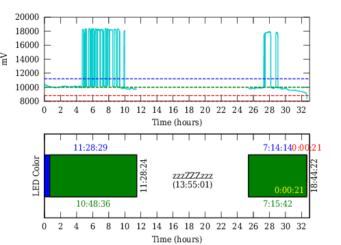
Nearly 19 hours! That's pretty good! We can see huge spikes in the graph where we're in direct sunlight and the panels overpower the batteries. At this point, with some clever circuitry, we could store that energy. Unfortuantely that's something we've not sorted, but now we know it's probably doable.
A second trial shows similar results. The sharp eyed here may notice that there's no red time, that's because it actually slept a second night and powered on the next day for another 17 minutes until the batteries died. At 10 AM those windows aren't in direct sunlight yet to keep it going, so for plotting reasons I left it off. Over 19 hours!
You can also see a slight increase in voltage from 24 to 26 hours, which I believe are the panels coming into direct light providing more current to offset the draw from the batteries. A Model A would have been entirely solar powered that day. It's definitely feasible to power a Pi off solar.
So to summarize:
Bigger panels are better, but even little ones can help. Get the panels positioned so that they're in direct sunlight for as long as possible. Provided the panels are powerful enough, they will still help even out of direct light, but it's exponential. It'd be good to charge the batteries when there's extra power, because there clearly is here. We'll let you know if we sort it.
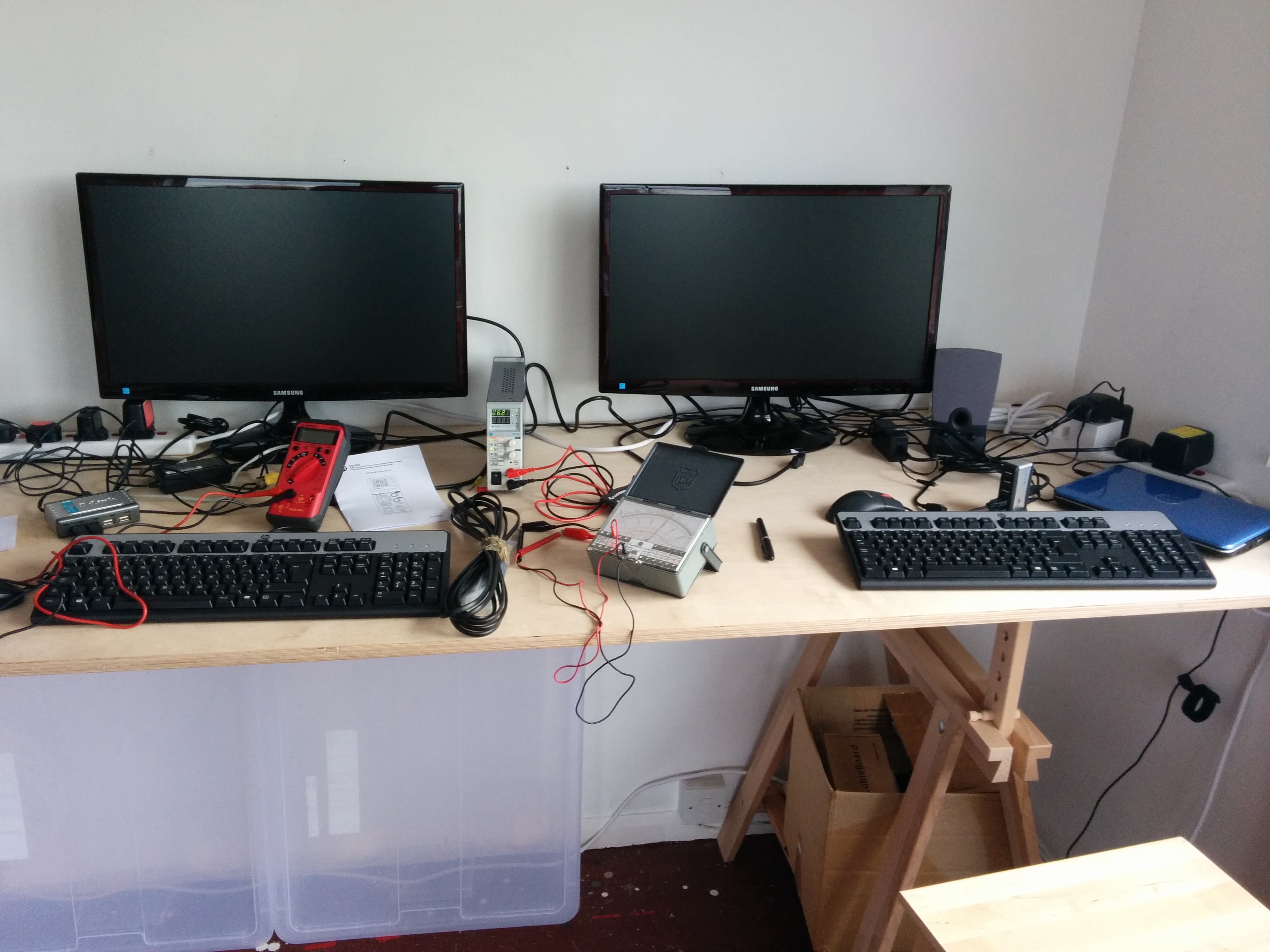
7.3. Methods in the Madness: Debugging and Software Development
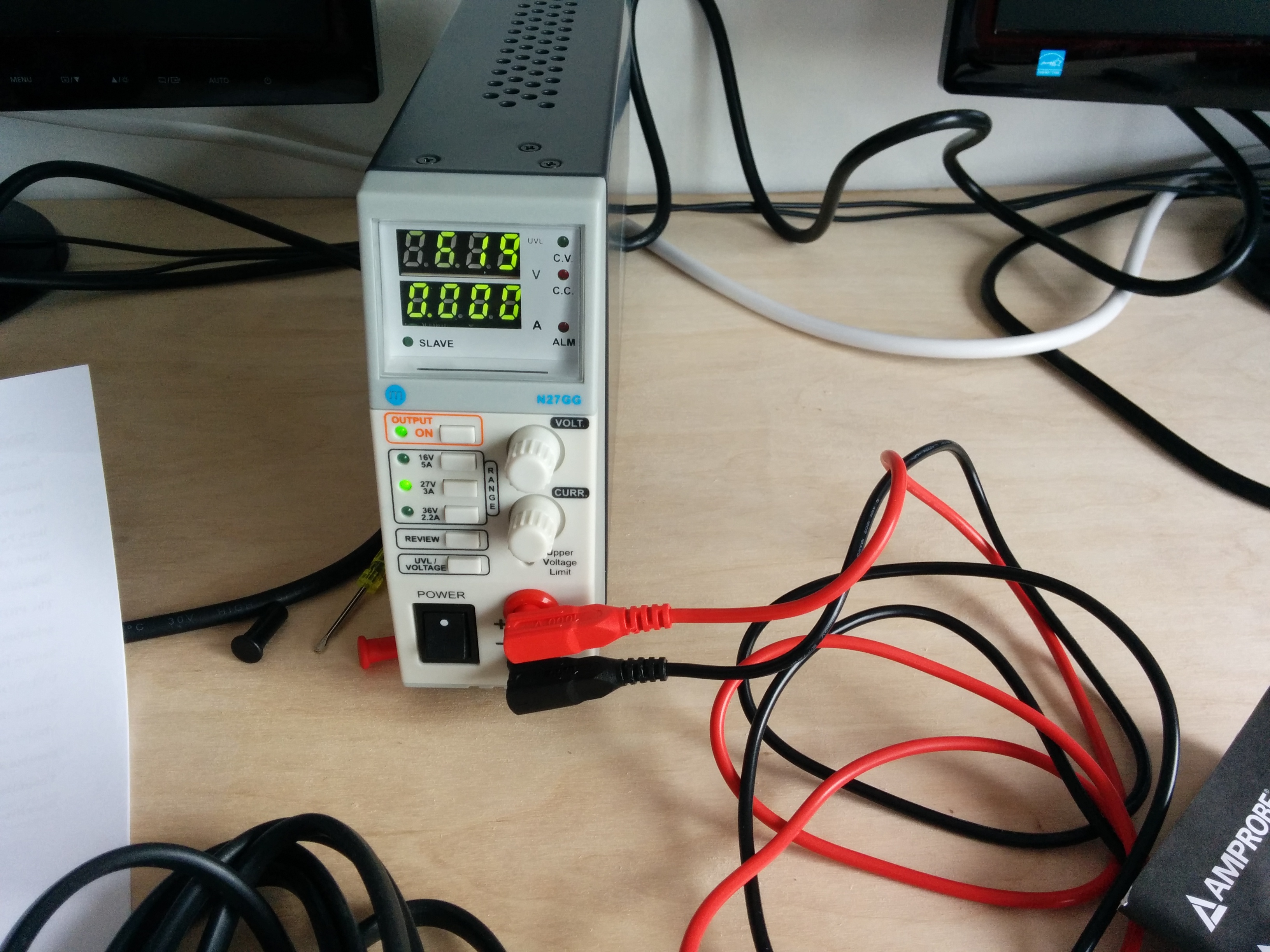
Most of our testing used external power supplies to make the development cycles faster. (Well, would you want to add "wait for the batteries to discharge" to every edit/compile/test loop?!) Check out this large humming monster:
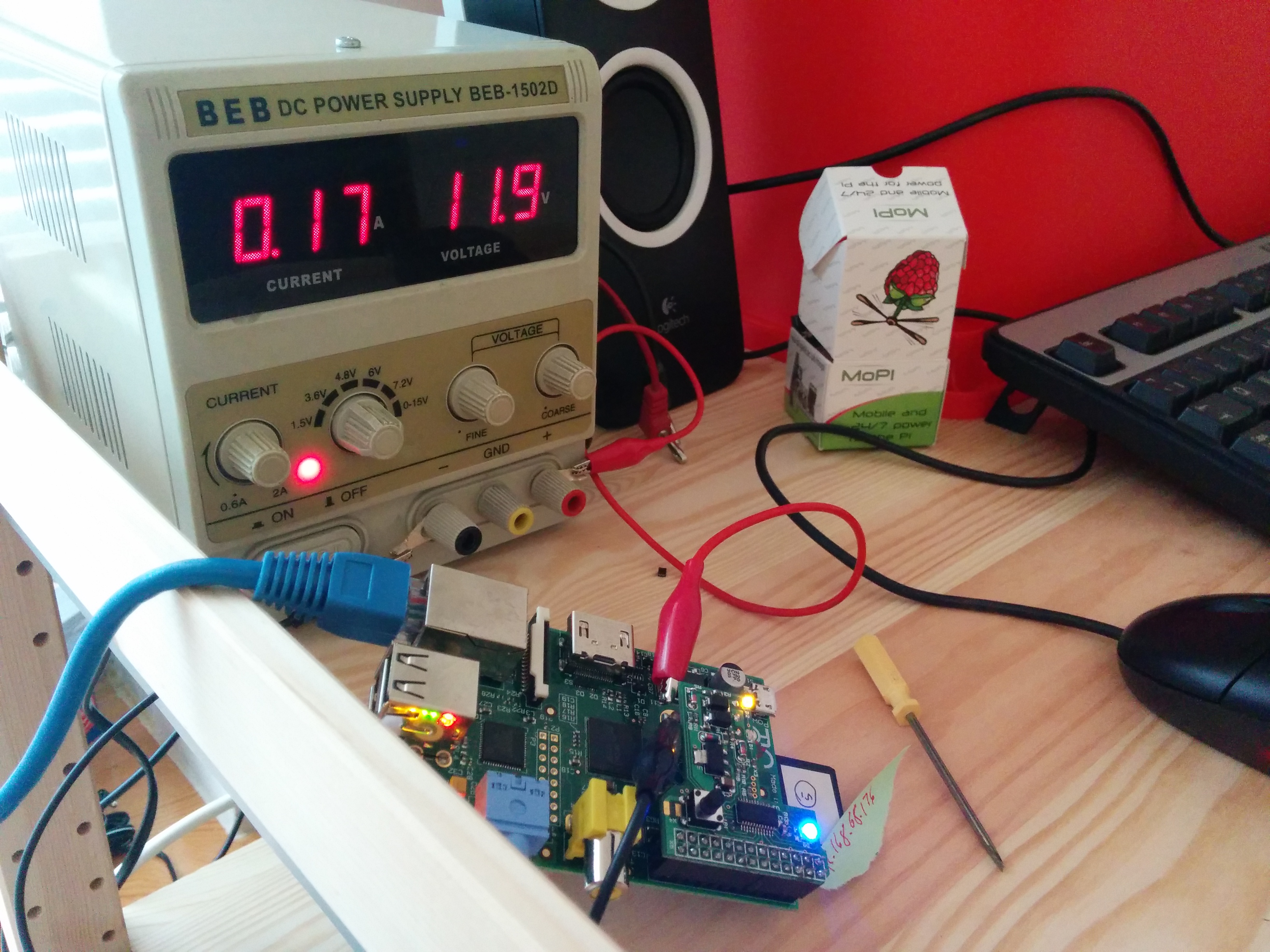
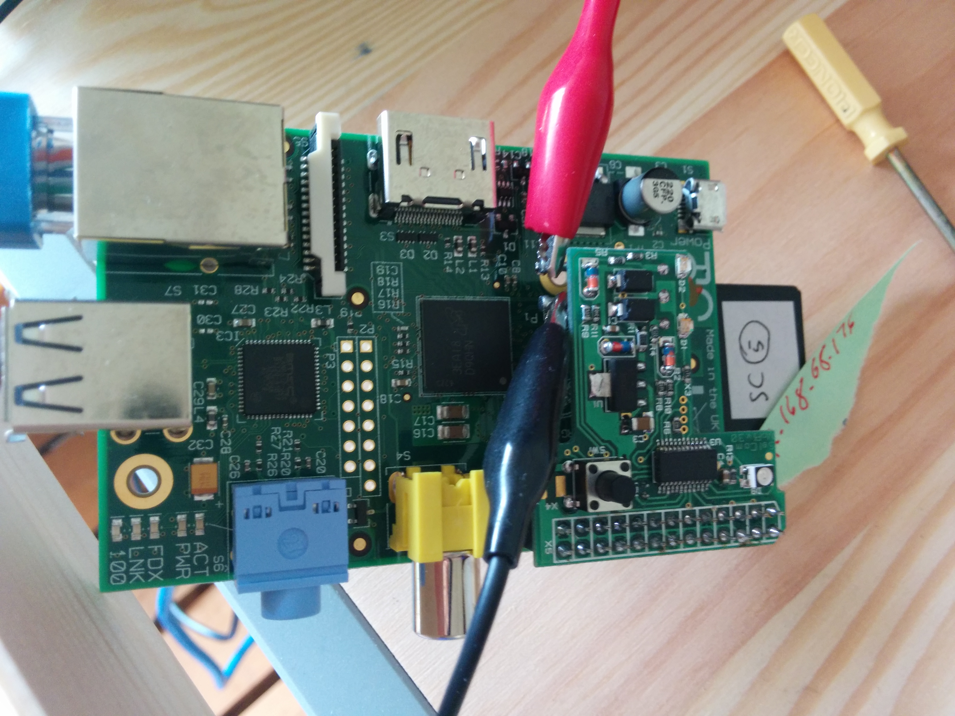
The Pi is drawing 170 mA; MoPi is getting 11.9 volts from the PSU. The PSU connects up to one of MoPi's supply inputs using a couple of re-purposed panel pins:
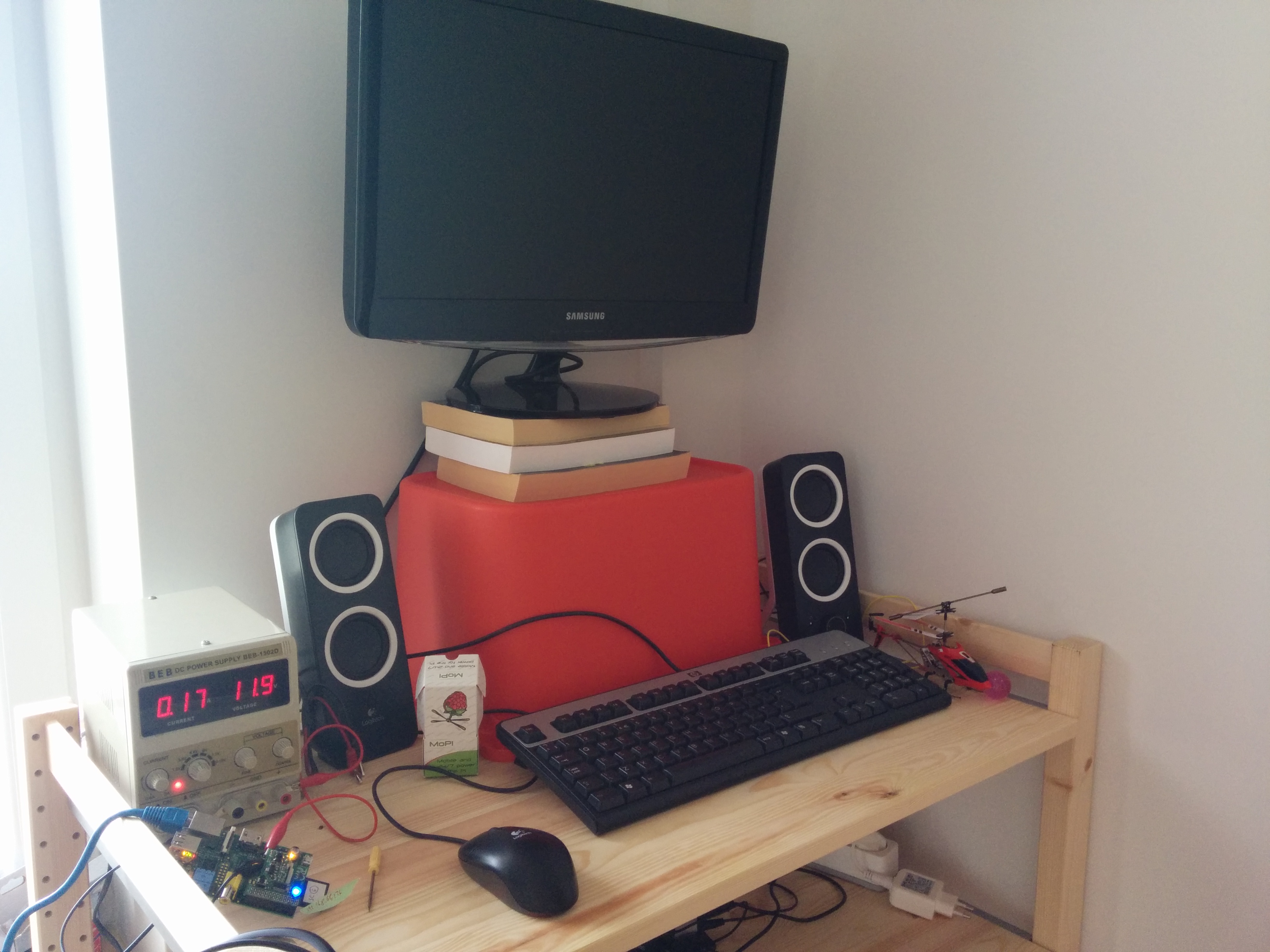
Mission control (helicopter not strictly necessary):
We've also got a flash new PSU down at the workshop:
And here's Fred after I just showed him the bill:
While we're showing my snaps, here's one of my absolute favourite bits of kit ever:
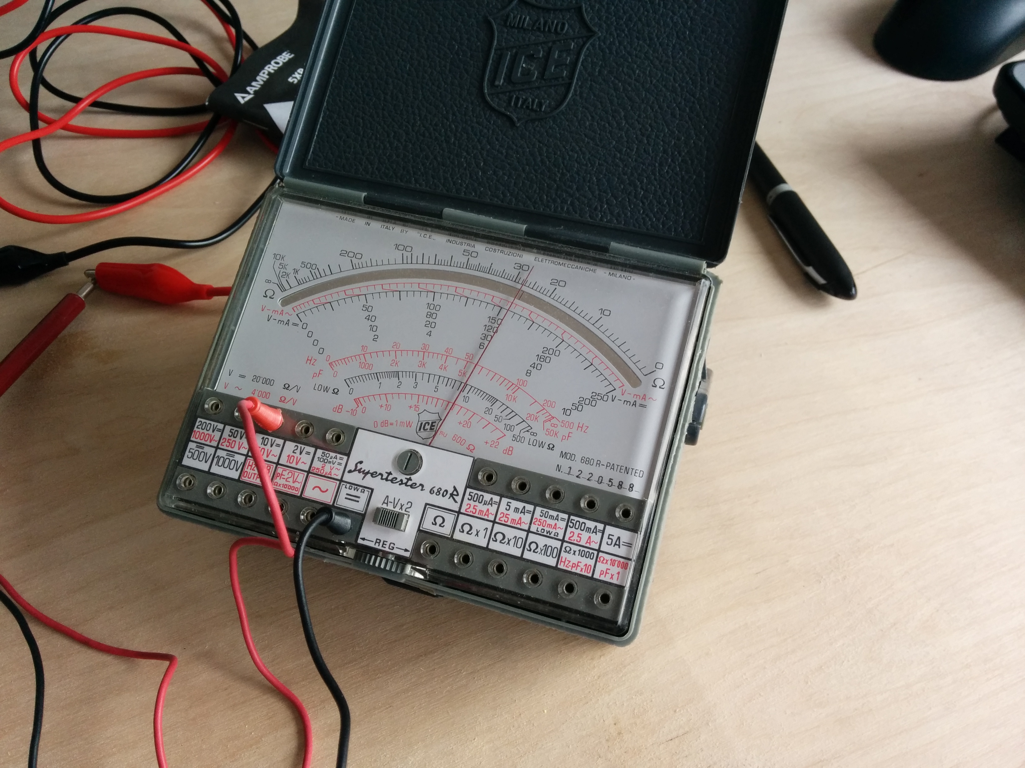
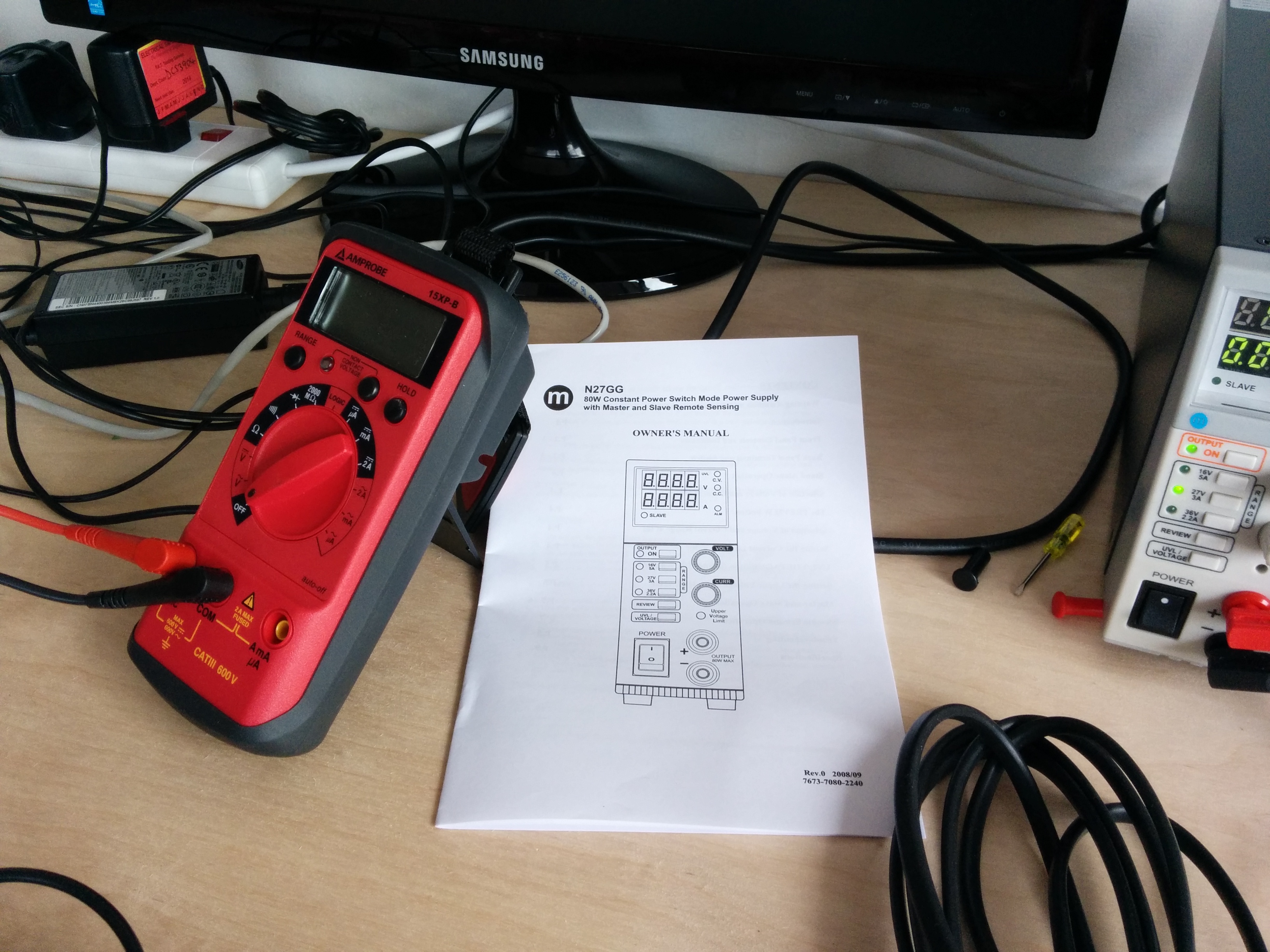
This multimeter has been running reliably for 30 years! Ok, at some point I couldn't get the batteries any more, so I had to bodge up a container for a different size, but apart from that it has been pretty much perfect. I plugged it into our new PSU, dialed up 6.2 volts and hey presto! The meter and the PSU agreed 100%. Can I marry my multimeter?
We've got a new shiney one too, but the romance just isn't there:
In early testing we often reached states that caused error conditions of one sort or another on the Pi. For example:
- The green indicator LED repeatedly blinks three times when the loader.bin bootloader file is not present — in our case this was because a hard power shutdown caused corruption of the SD card.
- The red power indicator LED may blink if the battery charge is very low and it is failing to drive the Pi (and if the microcontroller is not properly shutting down the regulator).
In cases like these the Embedded Linux wiki page on RPI troubleshooting is your friend! Another useful part of the Pi-oneer's toolkit is the excellent NOOBS setup from the Pi foundation, which makes it easier to restore your SD card after failures.
But inevitably the life of electronics prototyping brings its fair share of mystery — why have my GPIO monitoring pins all gone low, all of a sudden, when the indicator LED and the microcontroller still work? Cue much head scratching and serious faces. Followed by a session with the debug header and the diagnostics rig on the microcontroller — and it turns out that a single page of memory (which happenned to contain the code running the IO pins) has been wiped, presumably by power fluctuations at the low battery state. Time to add some more diodes!
And here's a typical gotcha:
- Step 1: have the bright idea of reusing the battery totally empty state for the shutdown button pressed state.
- Step 2: implement the code changes in the daemon and install. Reboot.
- Step 3: oops, my Pi just shut down as soon as it started. Hmmm.
- Step 4: oh yeah, that's also the default state of the GPIO pins when the MoPi rig isn't connected. Ah. That means that my Pi is going to shutdown every time I start it up. And Lubo just took the prototype boards back to the lab. Um. Looks like the Donkey of the Day award is coming my way again.
- Step 5: waste half an hour remembering how to mount the SD card read-write on another machine and manually editing the daemon.
We learn from our mistakes — that's why I make as many as possible.
Finally, the current author has found it useful to run around in circles, screaming and shouting. (It doesn't fix the electronics, of course, but if you're lucky it generates sympathy in those around you, or at least a desire on their part to give you a beer to shut you up.)
8. In the Wild: Applications
Want to strap a hackable GoPro-type cam to your skiing helmet? Or make a Wii-type remote and splash virtual paint onto your devices? Or measure atmospheric pollution in the garden with the AirPi sensor kit? The Raspberry Pi is a great platform for these types of applications, but you'll need a mobile power supply when you get out and about away from the wall socket.

If you've been following The Story of Pi these last couple of years you'll have come across 1001 power supplies — from batteries to solar panels, from car connections to water turbines. The Pi was designed to give a boost to science and technology education, and it has already made a huge impact — here in the UK, for example, we have a shiney new computing curriculum in the works. There a whole load of reasons why we need to educate our kids about technology, and how technology can help them cope with the challenges that the future holds. And not just any technology — the Pi has a low carbon footprint and is made in the EU.
The MoPi Kickstarter offered three Pi outdoor experimenter kits to help teach the links between technology, climate, wildlife and the like:
- Outdoor Adventurer Kit
- Outdoor Experimenter Kit (Light)
- Outdoor Experimenter Kit (Light and Air)
Then there's various projects that our backers have started (yours not here? send us a pic!).
We'll detail them here to give a flavour of the applications of the thing, but really the sky's the limit: every mobile Pi project has a place for MoPi.
8.1. Outdoor Adventure Kit
The base level kit has everything you need to get out and about: a Raspberry Pi Model B, case, SD card, and a MoPi board with NiMH batteries, holder and charger (and a wall supply for when you get home!).
8.2. Outdoor Experimenter Kit (Light)
This kit has all of the previous one, plus the Raspberry Pi camera module (day or night versions). Ideal for all types of outdoor motion-sensing and photography projects. If you haven't tried the excellent Pi camera yet here are a couple of examples:
Forest Gump came by the office when we were testing an early battery-powered camera rig (a hackable "GoPro"?!):

The next olympic downhill ski champion straps a Pi cam to his head:

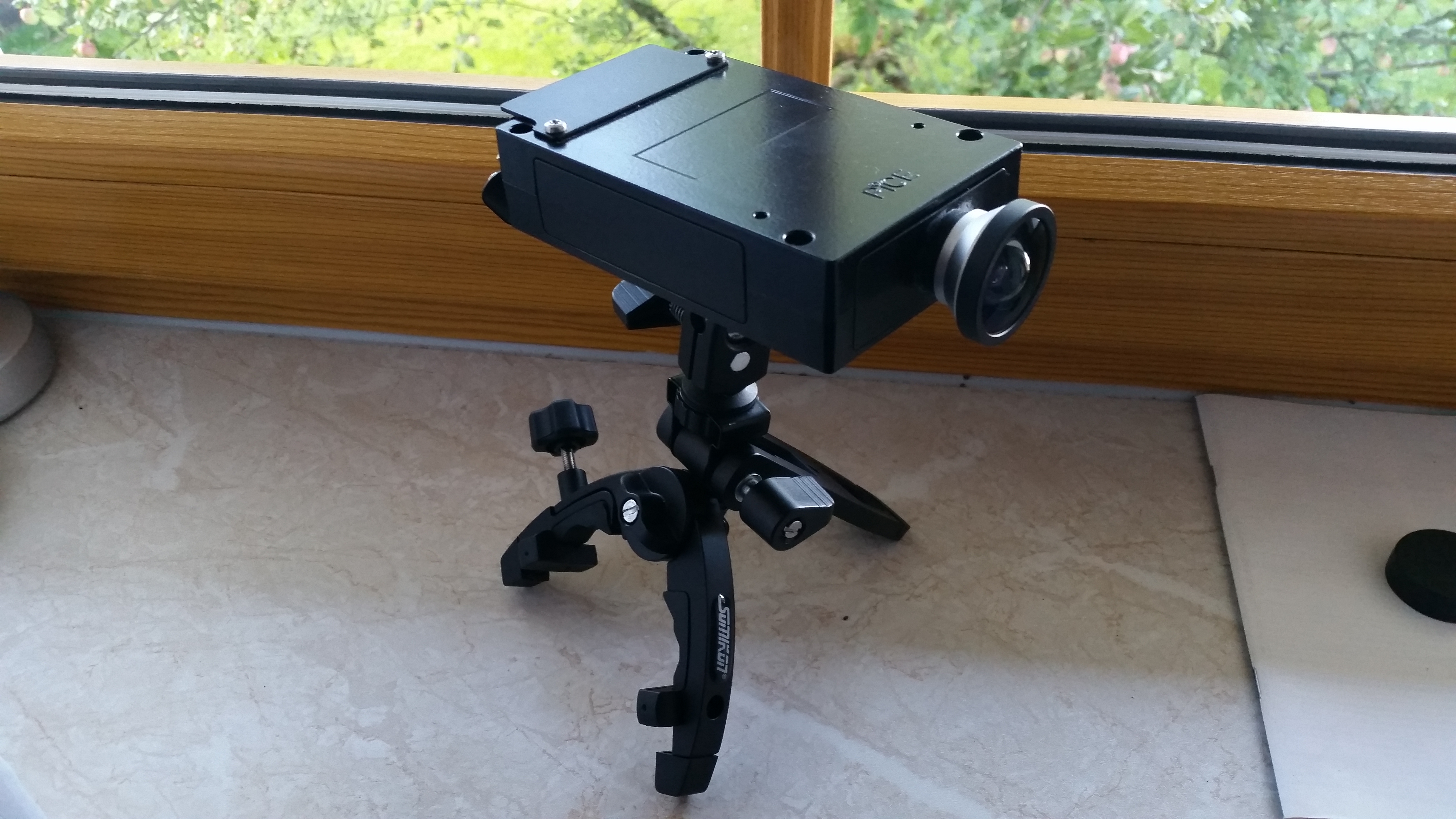
Here's the camera rig:

People have done all sorts of stuff with these cameras — from videoing Teddy Bears in the stratosphere to night filming wildlife — the educational opportunities are obvious.
Where do you want to use yours?!
8.3. Outdoor Experimenter Kit (Light and Air)
If you watch the film Chasing Ice you can't fail to be amazed when a vast chunk of glacier the size of Manhattan suddenly disintegrates before your eyes. What are the climate changes that have triggered these massive events? How do they play out in the air we're breathing? How do you measure atmospheric conditions, and what science can we use to explain changes in those conditions?
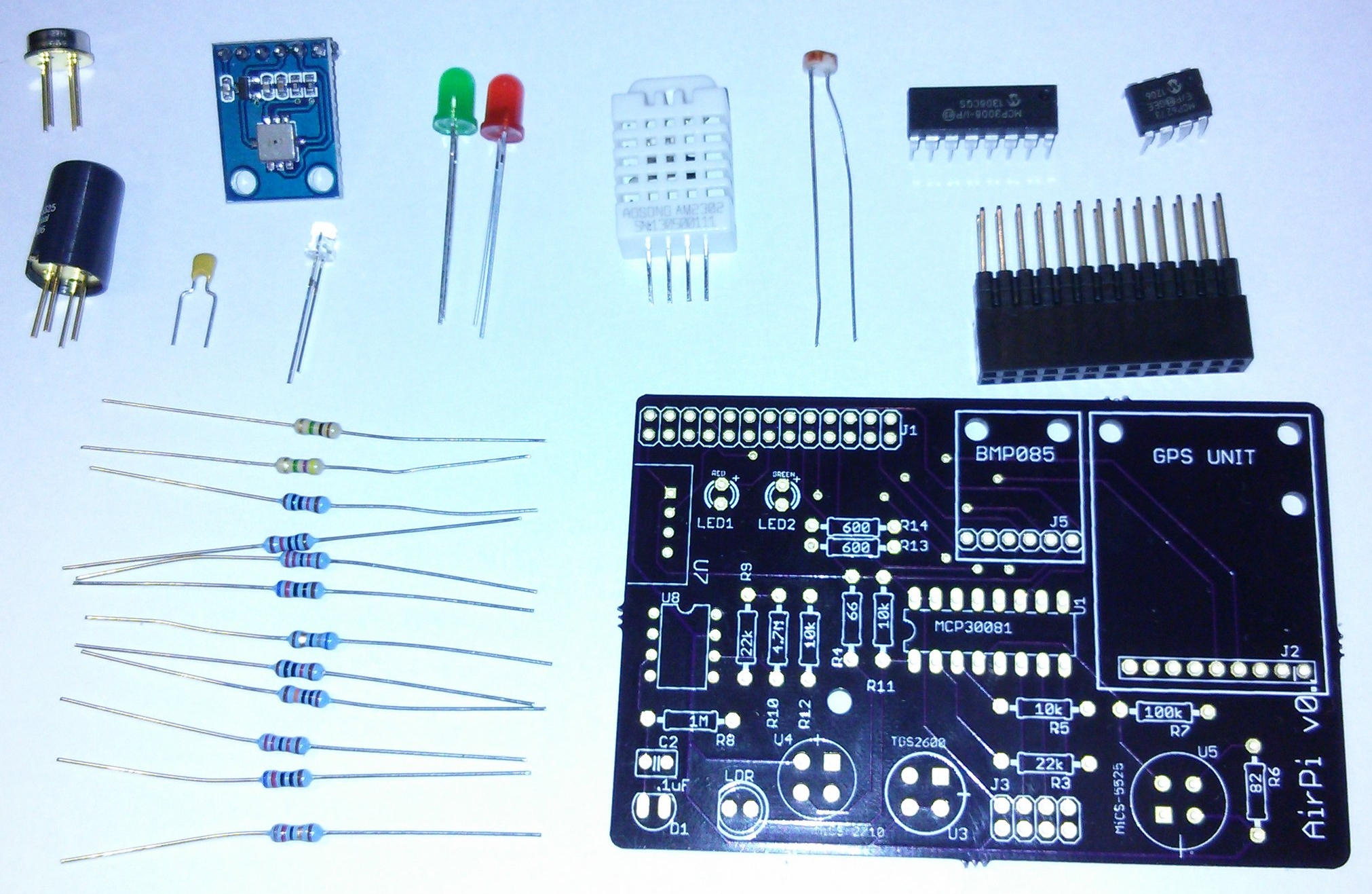
Meet AirPi, a brilliant Pi-based atmospheric monitoring kit that ran a crowdfunding campaign in 2013 and started shipping in the autumn. The Outdoor Experimenter Light and Air Kit includes an AirPi with the mobile rig, all set to get out and about measuring temperature, relative humidity, air pressure, light levels, smoke, and the concentrations of the harmful gas pollutants carbon monoxide and nitrogen dioxide, and plotting the results direct to a webserver running on the Pi.
Here's the AirPi board, sensor and indicator set:
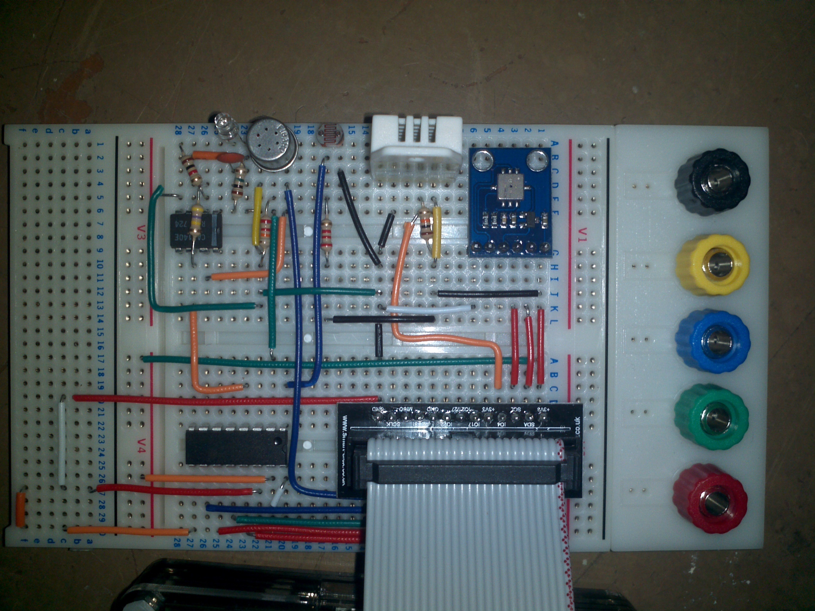
And here's one we built up on a breadboard:
From version 3 MoPi uses a different set of GPIO pins in order to avoid conflicts with AirPi (thanks Tom Hartley, creator of AirPi, for his help with this).
We've done a lot of work with AirPi and beefed up its software offering a bit — which Tom is going to include in the next official distribution.
8.4. Kickstarter Backer Projects
8.4.1. Night Camera
Thomas Farber's night camera:
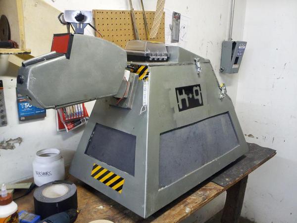
8.4.2. K9
Twisted Monk's K9:
8.4.3. Self-Balancer
Zachary Igielman's self-balancing gizmo with MoPi and RyanTeck's motor controller:

8.4.4. Garden Camera
Here's Alexandre Besnard's garden camera:

He's using the Pice case, and says "Pice is a great case for using the pi as a camera and I will use it to observe the evolution of some plants in my garden. Mopi is the perfect power supply."
Thanks Alexandre!
8.4.5. Remote Switch
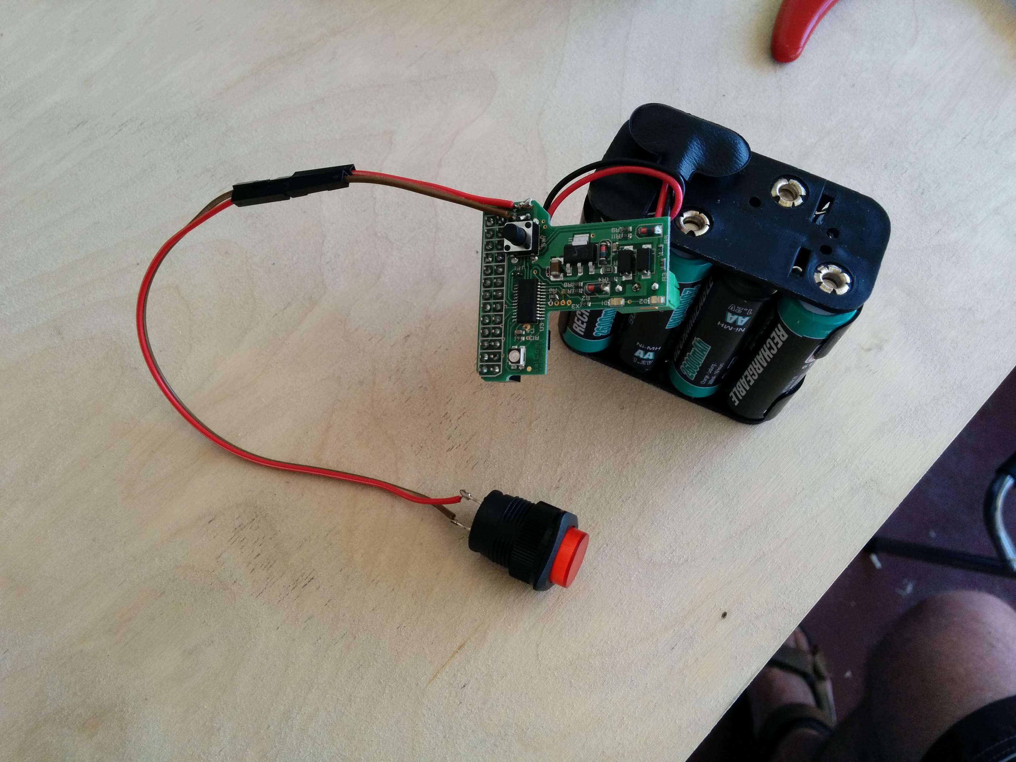
Daniel T, one of our Kickstarter backers, wanted to fit a remote power switch to his board. (It has one fitted, but if you're building something with a case and need the switch to be somewhere away from the Pi and/or MoPi then there are a couple of remoting pads on MoPi for the purpose.) Here's the result:
Daniel hasn't got the soldering bug yet :-) so I fitted one for him, and here are the pics...
It is an easy job — just wire up an SPST push-to-make switch to the two pads next to the power switch:
And voila:
9. Batteries, Holders and Chargers
Here are links to some of the batteries, battery holders and chargers that we've been testing MoPi with:
From RS Components:
From Farnell:
- x8 AA battery holder
- Duracell AA NiMH 2400 mAh 4-pack
- Energiser AA NiMH 2400 mAh 4-pack
- x4 AA battery charger
From Maplin:
10. Other Directions
10.1. A Possible Charging Circuit
One feature that we didn't manage to get sufficient backing for was battery charging. This feature would be a great addition to MoPi, but it turns out to be pretty difficult. :-( In fact, charging with lots of different chemistries may not be possible at all on a tiny device like the MoPi. (Most manufacturers of charging ICs only support one chemistry per chip, for example, and some only support charging a single cell per chip! Many chargers also rely on having a temperature sensor in physical proximity to the batteries themselves.)19 The other challenge is that we've got a really small surface area to work with on the PCB.
Still, a number of our backers want to use MoPi with a charger (e.g. to charge batteries from solar panels during the day and then run on batteries overnight), so we've been working on a configuration with an external charger. For example, here's how we think a UPS configuration with charging could look:
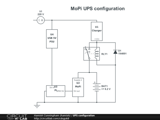
We haven't tested this yet, but it should work. ;-)
There are a number of potential gotchas in this type of circuit. For example, when the mains power drops, the Pi must be powered pretty much instantly in order to avoid triggering a reboot. There are no big capacitors on the Pi's PCB to buffer its consumption of 300-500 mA without power. To deal with this requirement we need MoPi to be always on and monitoring the Pi's 5V feed, even when that feed isn't being supplied by MoPi itself. (This doesn't waste much power as our microcontroller is very efficient.) When MoPi sees the 5V rail start to fall the controller immediately enables its 5V stabilizer, taking over supply of power to the Pi.
In the circuit above, when there is mains, the charger is generating e.g. +12V DC and the relay's coil is energized. The contact is switched to the normal open position and is passing +12V to charge the batteries. When mains drops, the relay is switching to the normal closed position and charging will stop. MoPi is powered all the time — and so, we hope, is the Pi. (What does the diode do? When the +12V goes down, accumulated energy in the relay's coil must be dissipated. The diode is shorting the coil to do that. Otherwise the relay's contact will stay closed for a longer time.)
More on this when we get time to test it out in practice.
In the meantime we've been working on various solar options... Watch http://pi.gate.ac.uk/ for updates.
10.2. Other Options
For voltage regulation another option is a UBEC20 — a device popular with radio-controlled aircraft people, and hence nice and light-weight, and also fairly cheap, e.g.: this one, this one or this one. UBECs are switched-mode regulators, just like our MoPi regulator board, so they don't waste power when converting high DC to 5 volt DC.
Some other useful links about Pi battery projects: on Raspberry Spy; on the Raspberry Pi Forums.
Gray Girling's Pi owners' manual also has a good discussion about battery supplies and their subtleties (and is generally an excellent investment for the Pi enthusiast).
11. Linux is Lovely
One of the great things about the Pi is that it runs a free and open source software stack. This makes development so much easier — and here's an example of why...
11.1. Glitches in the Pi's I2C Bus
The I2C bus is a great way to ship data between the Pi and add-on boards like MoPi. It is also a bit of a pig to get working: the CPU in the Pi has a hardware bug that causes intermittent bad reads from the bus. Quoting Renata Wolff:
The broadcom BCM2835 has a (hardware) bug in the I2C module.The BCM implements "clock stretching" in a bad way:
Instead of ensuring a minimum "hightime" for the clock, the BCM lets the I2C clock internally run on, and when it's time to flip the clock again, it checks wether or not the clock has become high, and if it is low, it does a "clock stretch". However if just in the few nanoseconds before this check the slave releases the clock signal indicating it is ready for a new clock, the clock pulse may become as short as 40ns. (that's the lowest I'm able to measure, and that of course is quite rare). With a 100kHz (10 microseconds) I2C clock, the "bad" moments to release the clock are 5 microseconds apart.
(See also Gert van Loo's description here.) This took us a quite a few debug cycles to cope with! Below some details of one of the methods used (the others involving lot of sweating over a hot oscilloscope, trawling system logs and the like!).
11.2. Installing I2C
Now that MoPi uses I2C as its communication mechanism, we have to enable this in the simbamon package. Here's how we do it21:
- if i2c-tools isn't already installed, install it:
- sudo apt-get install i2c-tools
- (you might as well do the same with python-smbus for testing purpose)
- on older Raspbians (using modules):
- edit /etc/modules and add lines i2c-bcm2708 and i2c-dev
- edit /etc/modprobe.d/raspi-blacklist (if it exists) and comment out the line blacklist i2c-bcm2708 (by adding a # at the start of the line)
- on newer Raspbians (using device tree):
- add dtparam=i2c=on to /boot/config.txt
(The postinst script in our Debian package for simbamon does all this for you, by the way.)
11.3. Debugging with I2C Tools
The process of developing our interface involved hacking the i2c-tools package to play with the multi-byte read facility in the i2cdump command. On a closed-source operating system, of course, you would be stymied at this point. On Linux it is super easy :-)
Here's how to pull down the source code, rebuild and test:
- edit /etc/apt/sources.lst and add this line:
- deb-src http://mirrordirector.raspbian.org/raspbian/ wheezy main contrib non-free rpi
- then
- sudo apt-get update
- mkdir i2c-tools
- cd i2c-tools
- apt-get source i2c-tools
- then make will recompile (the tools are in the directory tools)
Hey presto, I can hack away at the C code and get immediate feedback with commands like sudo tools/i2cdump -y 1 0x0b i (where 0x0b is MoPi's designated I2C address — the smart battery address)22.
Footnotes
- A huge thank you to Bo Meson, Fred Sonnenwald, Gen Gorrell, Vladimir Marinov, Georgi Marinov, Louise Illien, Julian Briggs, Caroline Ivimey-Parr, Angus Roberts, Joe Polifroni, Todor Primov, Anthony Toole, and all our Kickstarter backers!
- We quote a 20V max voltage to leave some headroom. We've run the board up to 25V but don't recommend it as a general rule.
-
A lawyer questioning a doctor during a trial:
Q: "Doctor, before you performed the autopsy, did you check for a pulse?"
A: "No."
Q: "Did you check for blood pressure?"
A: "No."
Q: "Did you check for breathing?"
A: "No."
Q: "So, then, it is possible that the patient was alive when you began the autopsy?"
A: "No."
Q: "How can you be so sure, doctor?"
A: "Because his brain was sitting on my desk in a jar."
Q: "But could the patient have still been alive nevertheless?"
A: "It is possible that he could have been alive and practicing law somewhere." - Ignore errors related to kmod.
- This warning means MoPi is not attached or not powered up: "/usr/sbin/simbamon: /usr/sbin/mopicli not working; MoPi not attached or powered? (mopicli. I2C bus input/output error on read word. Check bus? Check connection?)".
- RGB: red, green and blue. For us, Blue means you're fully charged. Green means things are OK. Red and you should be either preparing to shutdown or replacing batteries.
- Note that when MoPi powers up the Pi, it then waits 60 seconds for the boot process to finish. During this period power off requests will be ignored.
- Our Configuration Tool is a command line user interface, similar to raspi-config.
- The keen amongst you may know that the Pi can, in fact, run on 3.3V — more on that later.
- Again confusingly — this will become a theme — the names of the files as they live in the source package are different from their names when installed. If you don't like being confused, you might want to avoid talking to computer people as a general rule. For example, the MoPi board works on milivolts; the I2C communication uses centivolts; the user interface uses volts; the API uses milivolts. And all for good reasons!
- And no one complained about the whitespace rules! Who'd have thought it?!
- In common with most daemons, simbamon is written in shell script.
- Configuration provided by the user overrides the jumper for the current power cycle — and beyond, when simbamon is running as the daemon it will persist the config values. The firmware reads the jumper at each power up and initializes the cut-off points with Ni-MH or Alkaline values.
- The main archive (for stable releases) is at https://launchpad.net/~hamish-dcs/+archive/pi-gate with a development snapshot archive at https://launchpad.net/~hamish-dcs/+archive/pi-gate-snapshots.
- ADC: Analogue to Digital Converter.
- Prior to version 4 a three-bit coded voltage level is sent to the Pi over GPIO using WiringPi pins 4, 5 and 6 (physical pins 16/18/22).
- Note: a flashing yellow LED for a low supply will not reset until that supply has been disconnected for a few seconds and then replaced with a good supply.
- This is an old USB 1.1 device, which means it's current draw is limited by the spec. It's not too high.
- We like our backers. We'd rather not incinerate them if not completely necessary.
- UBEC stands for Universal Battery Elimination Circuit, which is rather a misnomer as they're often used to regulate battery supplies. Hey ho.
- The key steps are described in various places, including on Adafruit.
- For a revision 1 Pi — the very early boards — use 0 instead of 1.
