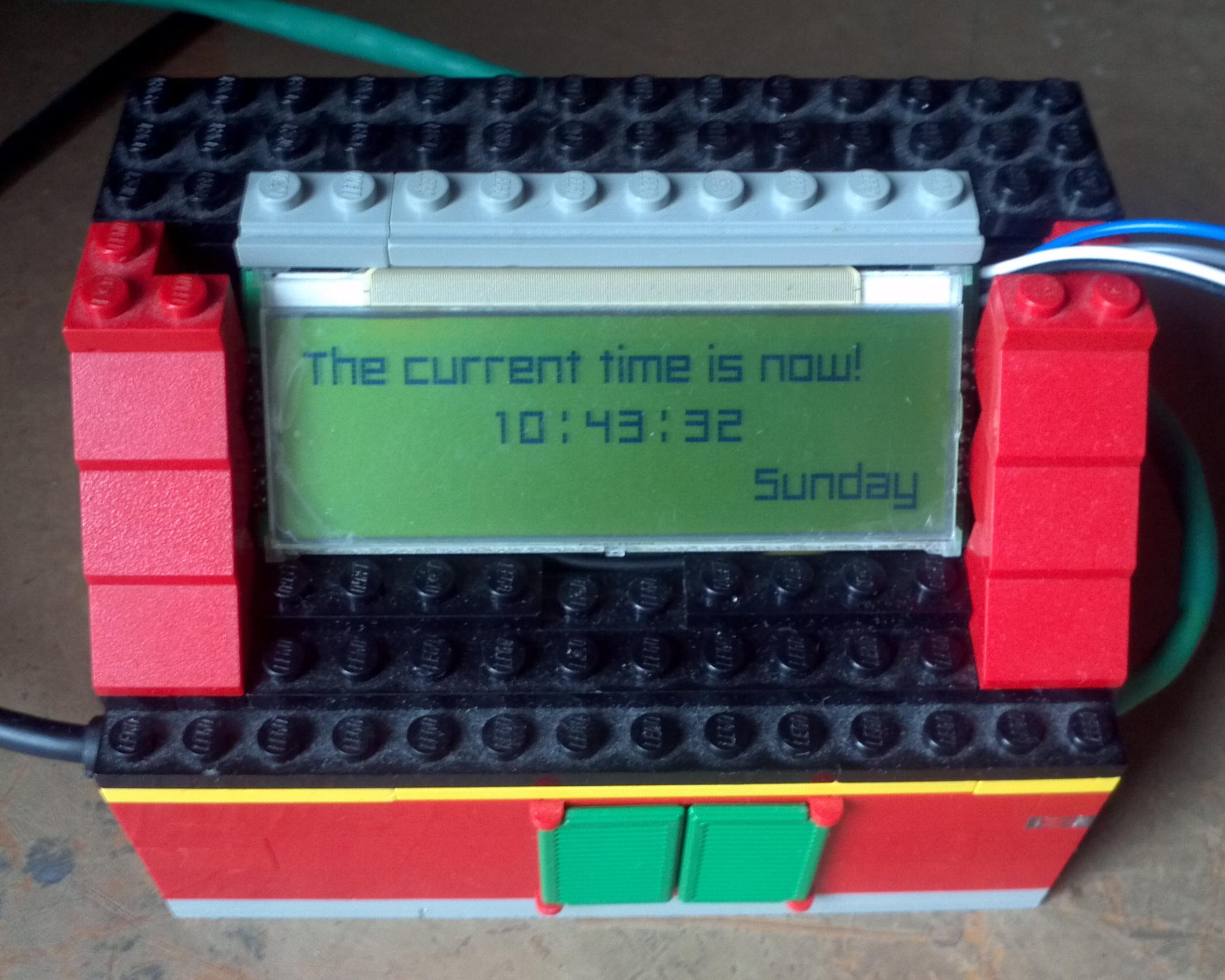
A year or two ago I connected a small 132x32 pixel LCD display to one of my Raspberry Pis. The idea behind it was that I could use it to display small status updates or anything else I wanted. Mostly from that aspect it ended up being a clock.
Once I got some code written for text, my next thought was "could I do video?" There were a few hurdles there to overcome as well. Codec? Framerate? I ended making up a solution where I read in 2-bit (black and white) bitmap image and displayed it. Repeat 24 times a second and you have video.

I noticed something interesting though, in that I could push out images a lot faster than 24 FPS. I could reach just over the 120 FPS. This is the magic number for what's known as active 3D TV. In Active 3D, the special glasses effectively blank out one eye than the other rapidly. At the same time the TV is showing the left eye, right, left, right, etc., at the same speed. (3D in movie theatres, for example RealD 3D, typically uses polarized light.)

There are two ways that active glasses are controlled by TVs. The first, impractical way is radio. Typically Bluetooth. The other way, which fits right in the realm of hacker electronics, is Infrared. (Just like a remote control!) Knowing this then I needed a was an infrared transmission from the Pi to the glasses, and then to match this up with the software I'd already written to display video. The latter, is easy. The former, not so much so.
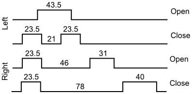
The first stumbling block is the infrared transmission signal. Like a remote control, it's also a specially coded signal. And like for TVs, many makers have different signals for their glasses. Fortunately, someone has already made an analysis of the different signals using an oscilloscope. I managed to find a reasonably priced pair of nVidia 3D glases. The protocol for them looks like this:
Unfortunately the timing of those infrared pulses is in microseconds. This is a small problem. The Pi can't consistently execute code at microsecond timing. Millisecond's about the best it can do because Raspbian isn't what's called a Real-time operating system. It spends a lot of time instead cycling between different tasks, any of which can call for CPU time at any moment and interrupting whatever else is happening.
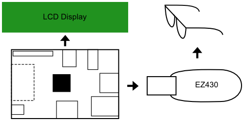
In a real-time situation like sending a infrared signal, we can't have the kernel deciding to take a pause in the middle to do something else. Fortunately, most microcontrollers are real-time, and so will do exactly what you tell them to in the order you tell them to. More Than User used an attiny45 to create an infrared remote. I haven't got one of those, but I do have a EZ430-F2013 which is this crazy TI micro-controller in a USB stick format thing.
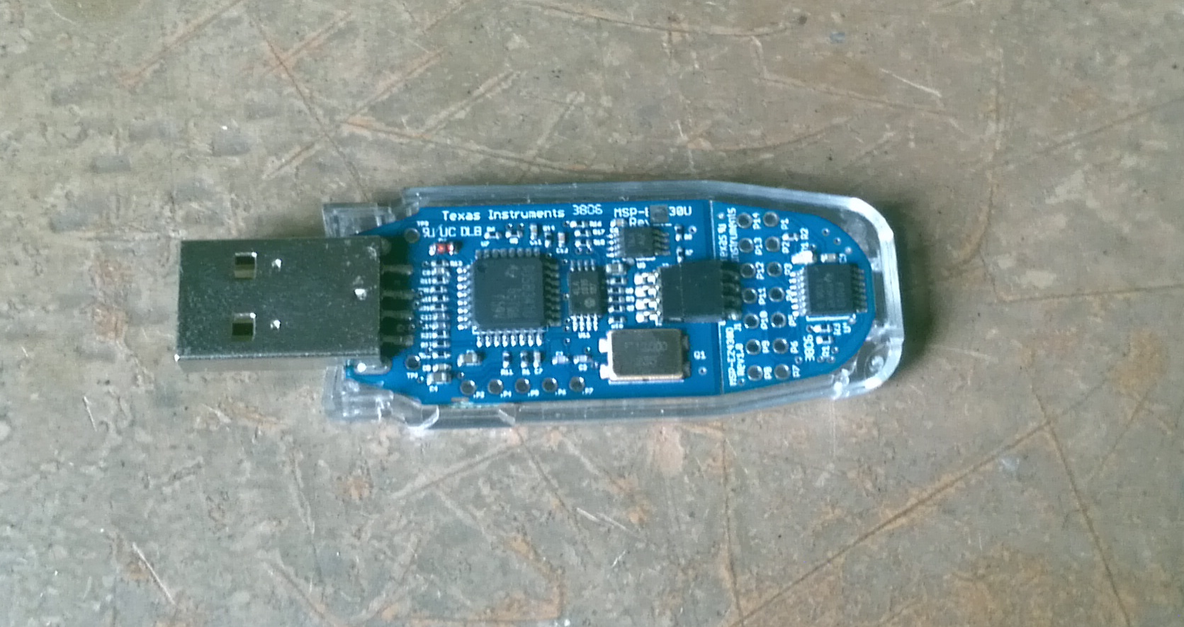
The EZ430 is very nice in that it comes with a proper development environment and a "let's blink the LED" code example—blinking an Infrared LED is what I wanted to do after all! What I really needed to do then was to learn how to control blink timing precisely. Things now get a little technical. Microcontroller programming isn't exactly easy and this was new ground for me.
Eventually I learned that the EZ430 has an onboard 8 MHz clock crystal. What's neat about this is that you can do something called a timer interrupt. There are different ways to go about it, but in general in this case I tell the EZ430 to count down from X to 0, which X is the number of clock ticks. If I could put in the number 8,000,000 for X, I'd have an exact timing of 1 second.
It's not quite that easy though. The counter is only a 16-bit integer which means I can only count down from 32,767. Fortunately there are clock dividers available which let you tweak it around. The catch here is that the protocol has halfmicrosecond timing. That means I can't divide down directly to 1 MHz timing, and instead can only divide down to 2 MHz timing. My counter then has to be twice the numbers shown in the protocol diagram.
// set up the timer
DCOCTL = CALDCO_8MHZ;
BCSCTL1 = CALBC1_8MHZ;
BCSCTL2 |= DIVS_2; // divide by 4
TACTL = TASSEL_2 + MC_1 + ID_0;
At this point I could control the glasses! I was thrilled! The next challenge then arrises: connecting this to the Pi. Enter input pin interrupts. The EZ430 has 8 digital input/output pins. One of them is used as an output for the infrared LED to talk to the glasses. Another pin I changed to an input, and then enabled a rising edge interrupt on it. This means as soon as voltage at the pin is detected it triggers a code call. From this I can then start the timer and open one eye and close the other.
// setup interrupt on pin 3
P1IE = BIT3;
P1IES &= ~BIT3; // rising edge
_EINT();
Hurrah! I connect the input pin on the EZ430 to a GPIO output from the Pi and I have glasses control. Now in my video program after a frame is drawn I simply turn the connected GPIO pin on and off again, triggering an interrupt on the EZ430, which ends up sending an infred signal to the glasses. Gives a very good feeling. It may have taken 10 minutes to read this far but it took hours to learn what I needed on the EZ430 on work it all out.
Unfortunately, my 3D TV doesn't work. As near as I can tell all the electronics are fine. I just missed one thing. Despite the fact that I can push out 120 FPS to the LCD there's still a lag for the crystals to change (this is the "response time" you might have seen advertised on your monitor). The timing on the little LCD I installed is far greater than the 8 milliseconds needed. Maybe there's a way around needing 120 FPS for the glasses, but I haven't exactly worked it out yet. So far now the bits and pieces sit on my desk. A good idea and fun to do. Close yes, but no cigar.
comments powered by Disqus