An AirPi is an open hardware environmental sensor platform. Weather and air quality monitoring using low cost components that you can order and then assemble yourself. Really it's a pretty neat project. What they do is give you a component list and a schematic diagram (and PCB layout too, if you're into that) so that you have quite a deal of flexibility in what your monitoring station can do. The complete list includes:
- Air pressure
- Temperature
- Humidity
- Light level
- UV level
- General air quality
- NO2 level
- CO level
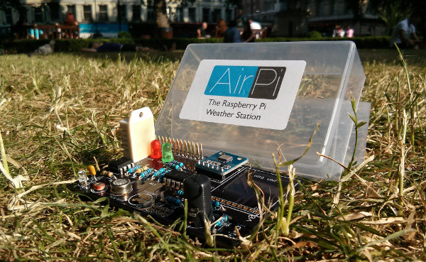 An AirPi promo photo...
Of course, what you build yourself almost never looks as nice as what the stock photo looks like. For starters, I know I haven't got easy access to PCB fabrication so I'm going to be building a breadboard AirPi. The first step to that is ordering components. On the AirPi site they give a good list of the components you need to have. Most stuff can be ordered easily enough either through places like RS Components or the rest off of eBay shops. Those were my sources, and in the end only one part (the UV sensor) had to come from outside the UK. I got a multi-resistor pack and breadboard from Maplin rather than eBay as that was a bit easier.
Keep in mind though that the component list on that page isn't exhaustive. I found out only on reading the assembly directions that a bit more was necessary, particularly to use the UV sensor you also need 0.1uF capacitor and a CA314 op-amp. The list also doesn't give all the resistors, hence the multi-pack from Maplin. There's no specific direction about what LDR (Light Dependant Resistor) either. Based off of comments in the forums I ordered a pack of GL5528, which have a light resistance of 10K-20KΩ and a darkness resistance of 1MΩ.
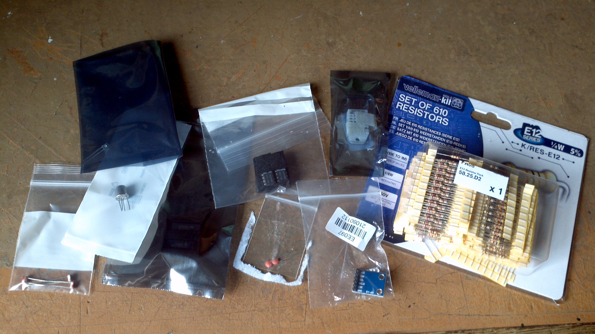 Here are all the components
In addition to all the bits above and the breadboard, I ordered an Adafruit cobbler clone and some solid core jumper wires so that I could at least do a tidy breadboard. I was unable to order the NO2 or CO sensors as the only folks who sell them are in the states and the shipping was killer.
So. On to building! Unfortunately, not all shipping times are equal and I wanted to get started playing so my first prototype only has the air quality sensor and the light level sensor.
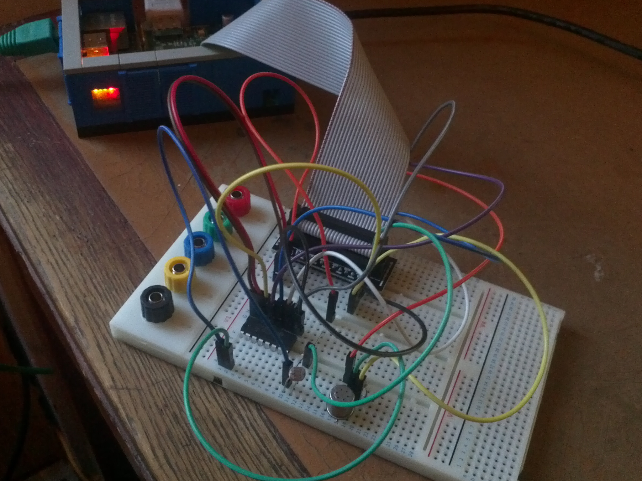 My solid core wires hadn't arrived yet either, so messy!
When almost everything had arrived, I started to build prototype 2. All I was missing was the UV sensor. By the time I finished building though, the sensor had arrived and I added it in as well. Working on the breadboard ends up being something of a logic puzzle. How do I get things where I want them, using a minimum of wire? Without short-circuiting? Or having things stick up? Despite already having some practice and familiarity with the circuit from building prototype 1, prototype 2 definitely took longer to build. Lots of cross checking several of the different datasheets. A digital multi-meter was a good friend as well.
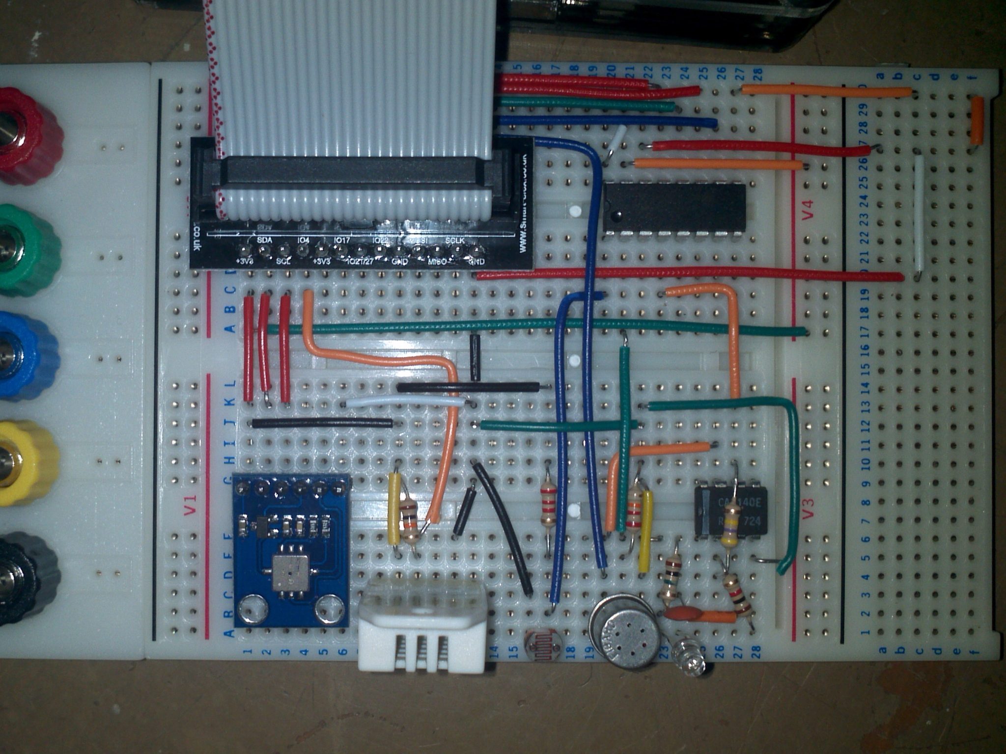 Much nicer!
All things considered the AirPi directions are really quite good. It took so long because it's a matter of having confidence that I'd done it right. Combine that with the logic puzzle of individual sensor placement. As the directions are given on a sensor-by-sensor basis, there's no sense of when you can connect things together to make a tidier circuit. The fact that you can jump from the +5V of the air quality sensor to the +5V of the op-amp is incredibly handy if you, like I've done, place them close together on the breadboard, and you notice it. Things like that that take up the time, and then cross-checking it to make sure it's right takes up even more.
Fortunately in the end I only had three real electrical mysteries (aside from plugging things in in the wrong spot). The first was that I misinterpreted what had to be done with the light level sensor. The directions describe its connection in text only and it just confused me. They make sense now though...
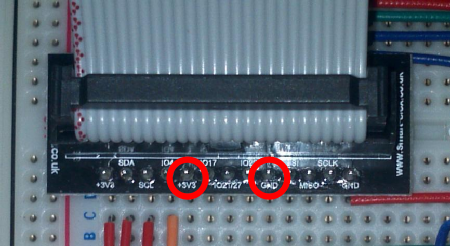
The second issue doesn't really have anything to do with the AirPi. The cobbler I've got has GPIO pins 9 and 17 swapped on the PCB labeling, and testing with a multimeter they seem to do neither. This is a ground and +3.3V fortunately, but connecting the ground on the pressure transducer to what may have been +3.3V accidentally... not so good.
 Backwards! Yikes!
My third electrical mystery was much more annoying than either of those two. The long story short is that I had the UV sensor plugged in backwards. The long leg goes to pin 3, and the short leg connects to ground. Unfortunately, to figure out this was the case I had to go and 'debug' the rest of the UV circuit. Which is fine in principle, until you realize that before I started this I had no idea how an op-amp worked or what it really does. (Yes, the name is kind of an indicator, but that really doesn't explain the electronics.)
Fortunately Chris Gammell has an excellent explanation that made about 60% sense to me. I'll see if I can summarize my understanding... An op-amp takes a voltage level (in this case from the UV sensor) and multiplies it (approximately) by the ratio of the resistors between it and ground and it and the op-amp output. This is done with a feedback loop over the input to output. Sort of. Anyway, the directions mentioning "470 times" is referring to this multiplication factor of the sensor output, and is why I could use 1KΩ and 470KΩ resistors instead of the 10KΩ and 4.7MΩ resistors they did.
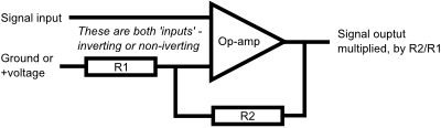 Roughly what an op-amp does...
There are other effects that come into play, I don't really understand all of this:
- As near as I can tell the multiplication works as the op-amp is really an oscillator. The resistor that links the op-amp output and the pin of the op-amp that's not attached to whatever it is you want to multiply causes, for example, an over-voltage. This triggers a state change to under-voltage. The resistor carries this back across which causes over-voltage again. This all happens very rapidly (oscillates!) and results in an even voltage thats the multiplied output.
- Chris' explanation has the signal being amplified attached to the "inverting input" while the AirPi has the UV output connected to the "non-inverting input". I think this has to do with how the UV sensor is a diode and we're connecting one end to ground.
- The capacitor in the circuit (not pictured here) has to do with stabilizing the feedback loop because of the response speed of the UV sensor.
- The resistor in parallel with the UV sensor ensures a minimum current level. The higher that resistor is, the greater the voltage because of Ohm's law 1/Rtotal = 1/Ra + 1/Rb. I think this explains that graph on the datasheet.
This brings me on to the thing I wish most from the AirPi project: an explanation of why and how things work. Right now it's a really nice monitoring tool, which you could use to learn about the environment. But it could be an electronics teaching tool as well.
But that's enough boring electronics. On to software! There's a set of directions on the AirPi page to get you started. It includes installing all the dependencies which is pretty good. I did all of that except for the 'eeml' steps - these are for connecting to Xively. This is the service AirPi uses for storing and distributing stuff. It looked a bit complex for getting started though, which is why I've skipped it.
Once the dependencies are installed and the AirPi Git Repository has been cloned, the first step is configuring AirPi.cfg. There's a bit more to it than the directions let on though. You may need to edit the I2CBus parameter, I had to change it to 1 to get it to work with my Model A. The UVI-01 ADCPin is incorrect with respect to the assembly directions, it should be 3 not 4. I also had to disable the MICS sensors as I don't have these.
There's also a small bug in Upload.py with regards to the AirQuality pull-up resistor. Line 118 should be changed from
airSensor = AQSensor.AQSensor(adc,AQADC,pullup)to
airSensor = AQSensor.AQSensor(adc,AQADC,pullup=pullup)Since I didn't do the eeml stuff, I also needed to comment out the eeml imports at the start of Upload.py. Once that's done though it runs!
Temp-DHT:       26.1 C
Humidity:       35.7 %
Air Quality:    16920.56
Light Level:    4.91 Lux
UV Level:       0.48 UVI
Temp-BMP:       25.6 C
Pressure:       97912.6 Pa
An AirPi built and running! The question is where we go from here? I'm planning to now collect data for a bit and see if I can massage it and get something neat out of it. What does Air Quality 16920 even mean? I'll want to check the calibration of the sensors in general and make sure it's not all nonsense. For example, I'll use some thermometers and a barometer to cross check those readings.
I'm also going to look into altering the software. A capability to log and display info without going through a third party service would be nice. I know the logging should be possible at least! I also just did a blog post about connecting a raingauge to the Pi. I'm pretty certain that can be added into the AirPi setup. Stay tuned!