Basics
Getting started with Pi-Tronics: adding electronics to your Pi
Hamish Cunningham, April 11th 2013
Contents
- 1. Interaction Electronics
- 2. Lighting Lights, Listening to Switches
- 2.1. Pins on the GPIO Header
- 2.2. Talking to the GPIO from Software
- 2.3. Reading from Switches
- 2.4. Putting it Together: Sensor plus LED
- 2.5. Getting a Buzz Out of Trannies
- 3. Parent Alarm
- 4. A Flood in the Basement
- 4.1. Hooking it all Together
- 4.2. Building and Installing
- 4.2.1. The Software
- 5. Books and Resources
- 5.1. Software and Source Code
- 5.1.1. Installing Pi-GATE Software
- 5.1.2. Installing WiringPi for Raspbian
- 5.2. Books and Sites about the Pi
- 5.3. Electronics Books and Sites
- 5.4. Circuits: Calculators, Simulators, Diagrams
- 6. Warning!
1. Interaction Electronics
The Pi is a general purpose computer. It runs GNU Linux1, which is an operating system used in satellites and phones, desktops and tablets, supercomputers and set-top boxes. It has graphics capabilities good enough for full HD video, plus computational power and memory sufficient to run a web browser or an office productivity suite. It has a good selection of standard interconnectivity options (including ethernet, HDMI, stereo analogue sound, and USB). Packing all of this into a very cheap, low power and low footprint (made in the UK!) device is truly game changing.
Another game changer with the Pi is its ability to connect directly to electronic circuits that can take readings from the physical environment and trigger actions in that environment (and/or over the network). When you couple a general purpose computing device with the Pi's extremely accessible interaction electronics all sorts of projects become so simple that everyone from school kids (Raspberry Pirates!) to absent-minded academic types can achieve them within a short space of time. This combination of general purpose computer with accessible electronics is a radical development. Welcome to the birth of Pi-tronics!
The Pi's connections for getting data from sensors and for activating external gizmos are called general purpose input output pins, or GPIO pins. The simplest of these will either sense or output a small voltage (3.3 volts, not enough to give you a shock!). We can connect simple electronic circuits to these pins to get the Pi interacting with its environment.
The Pi's GPIO pins are accessible via various software packages, which frees us from the tyranny of the keyboard/mouse/screen combination and allows us to program software to read from sensors and respond to changing conditions.
Below we'll give an introduction to sensing and responding with the Pi, and detail some projects that can be completed in a few hours with a few pounds' worth of materials. These projects will teach you how to couple the Pi's GPIO pins with easy-to-build interaction electronics:
- controlling an LED (hello world!) and reading from a switch
- hide! my parents are coming! (a simple alarm system)
- a flood alarm with text message notifications to your phone
These projects use a prototyping tool called a breadboard to get started quickly and easily. For introductions to this way of working, and to hacker electronics in general, see the electronics resources section.
Disclaimer: it is possible fry your Pi by doing this type of thing — please see this warning for details.
2. Lighting Lights, Listening to Switches
Pretty much the simplest thing we can do with the Pi's GPIO header is to light up an LED2 — let's make this our Hello World!3 example.
Materials used:
- a breadboard
- resistors (270Ω, 1kΩ, 10kΩ)
- green and red LEDs
- link wire
- a switch
- jumper cables
- a multimeter (optional)
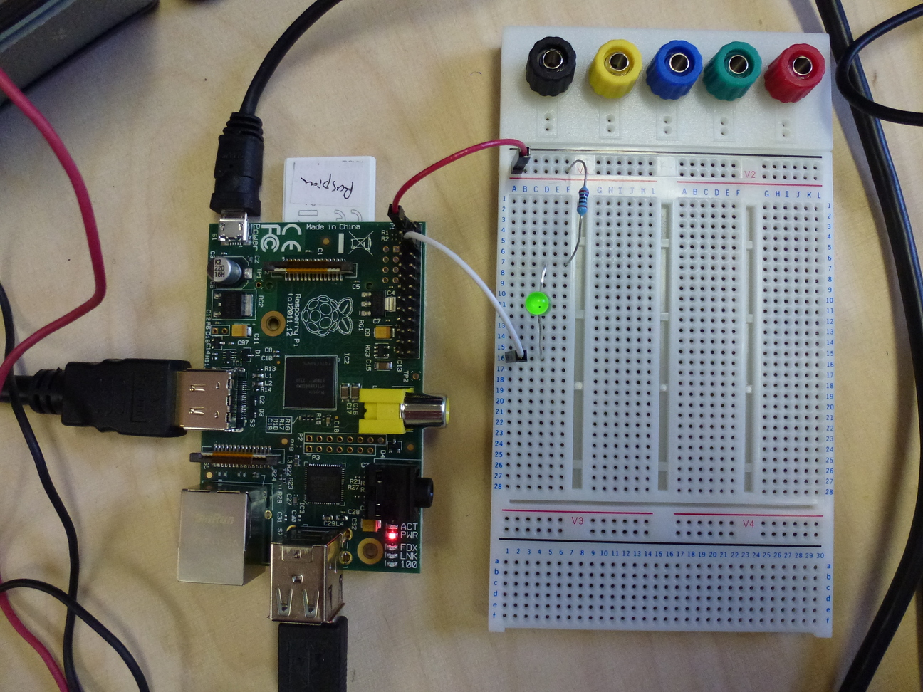
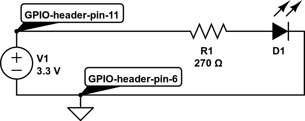
To create a Hello World! lighting circuit we only need two electronic components, an LED to light up and a resistor to prevent more current flowing through the LED than it can handle.4 Here's the circuit diagram5:

Here D1 is the LED we're lighting up and R1 is a resistor that prevents too much current flowing in the circuit. V1 represents the 3.3 volt power supply that the Pi makes available, with +ve on GPIO pin 1 and ground on pin 6. Note that I'm using the physical header pin numbers here as these are the easiest numbers to quickly match up to the Pi circuit board (just count left to right and top to bottom). There are several other ways to refer to the pins, however, and several gotchas along the way — for more detail see the discussion on GPIO pins below).
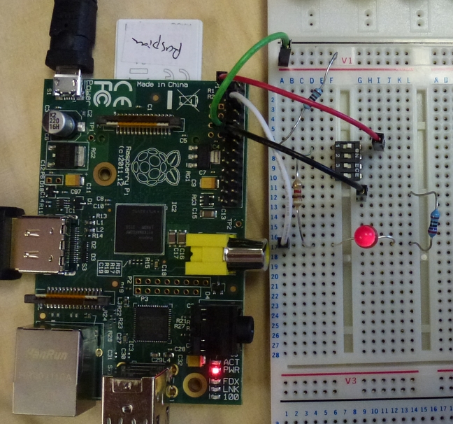
If we transfer this design onto our breadboard, we end up with something
looking like this:
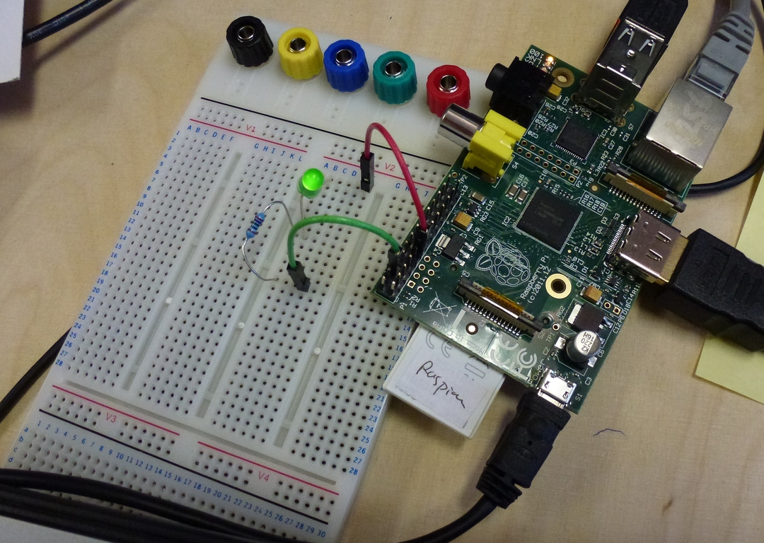
So far, so boring: this is pretty much the equivalent of connecting a torch bulb to a battery and going "ahhh" at the pretty light. More interesting, especially in the context of our earlier discussion on general purpose devices and interaction electronics, is to drive the LED by software; to do this all we need to do physically is connect the circuit to a different pin on the GPIO header, in this case pin 11. Now spot the difference:
Note the shift from pin 1 to pin 11 on the GPIO header. That's all! Now we're almost ready to start turning the LED on and off using software running on the Pi, but first we need to take a detour into the murky world of GPIO pin numbering. (If you're lucky enough to have your Mum nearby you may want to ask her to hold your hand while reading the next section. If it ends in tears don't say I didn't warn you.)
2.1. Pins on the GPIO Header
I think if I went on a course in Egyptian hieroglyphics for a month and then revised my obfuscated C notes for a while I could probably come up with a numbering scheme for the GPIO pins which was perhaps half as confusing as the existing one. Actually that's a little unfair, but the problem is that there are four separate ways to refer to the pins, all different, all useful. To begin with, there are two offical numbering schemes, one relating to the physical header on the Pi circuit board that we actually make connections to (numbered 1 to 26), and the other relating to where they interface to the Broadcom system on a chip at the heart of the beast (the BCM2835). Then there's also a name for the function of the pin (e.g. 'GPIO 0'), and an extra complication is that a couple of pins changed function in the 'revision 2' version of the Pi. Finally, the way that we access the pins through software also has its own nomenclature, and, because some of that software generalises across multiple devices (e.g. the Pi and the Arduino) again the numbering is completely different.
I think I'd need to add runes and Clingon symbols to the mix if I was really trying to challenge the supremacy of the confusion that can result here.
Luckily there are a number of good sources to turn to for help. My favourite
is from Gordon Henderson, creator of Wiring Pi, an
excellent software library for talking to the Pi (and several other boards). I
recommend printing out Gordon's key to the GPIO
pins and keeping it handy at all times. I also strongly recommend working
on the Pi with the pins positionned in the top right corner, not the other way
around, so that the numbers on the diagram match up with the orientation of
the Pi. So do not do the following if you value your sanity (assuming you
still have some left, that is6):
The Pi's GPIO facilities cover a lot of other useful functions that we've not
even hinted at so far. Consult one of the Pi books for details,
or see this nice summary one-pager from
Pimoroni, makers of the fabulously cute PiBow case —
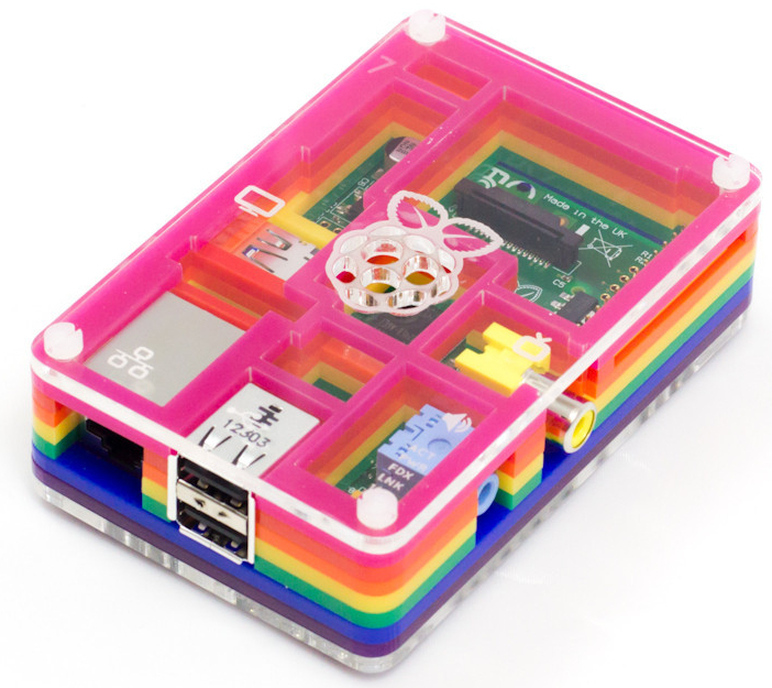
— and home of the
Pi logo's creator, Paul
Beech7.
2.2. Talking to the GPIO from Software
Now we're ready to write some software to control the interaction electronics that we're connecting to the Pi.
Although the Linux operating system running on your Pi provides access to the GPIO pins at a low level via the sysfs virtual file system, it is generally easier to use a higher level library that abstracts a little further away from the underlying hardware. Such libraries exist for (at least) Perl, Unix shell script, Python, Scratch and Java. We'll use the WiringPi library from Gordon Henderson, which makes available the same abstractions for various devices and is a well tested and robust piece of kit. (Thanks Gordon!)
WiringPi provides a convenient command-line program called gpio that we can use to control and read from the GPIO pins, and we'll use this in our examples. This means that we're going to be programming in Unix shell script, which is the command language that the Pi's Raspbian Linux operating system drops you into by default when you log in. This language can be used from the command prompt (the $ or # that appears on screen to prompt you to make an input) and can also be collected into a file and used as a command (or script) in itself. This makes it the most direct way to experiment with Pi programming (not to mention controlling many types of computer), and is well worth learning, even if you're also learning a higher level language like Scratch, Java or Python.
GPIO pins either listen for a signal (in input mode) or produce a signal (in
output mode). Our first job when programming GPIO interaction code, then, is
to decide which mode the pins we're working with should be in, and ask
WiringPi to set them up accordingly. Refering back to our circuit diagram,
we see that header pin 11 is what we're using to drive the LED —
i.e. make an output — and that therefore we need to set pin 11 into output
mode. For reasons discussed above header pin 11 is known to
WiringPi as GPIO 0, so we use the gpio utility to set the mode for that pin
like this:
gpio mode 0 out
We can read this as "call the gpio program to set the mode of pin 0 to output". (We don't need to do anything with pin 6, as this is always connected to ground and doesn't have a mode setting.) Next, let's turn our output pin on and see our LED light up:
gpio write 0 1
Again we're operating on pin 0, this time setting it high (to 3.3 volts — see next section).
And now turn it off again (to 0 volts):
gpio write 0 0
Magic!
For our next trick, let's get our Pi to sense something in the outside world, and respond to that input by again turning the LED on and off.
2.3. Reading from Switches
Let's recap where we've got to. First we hooked up an LED and a resistor to the Pi's 3.3v supply, then moved it onto one of the GPIO pins and discovered how to switch it on and off via software. Now let's look at an example of the other side of the interaction coin, reading from a sensor. To get us started we'll use a switch as a sensor, and get our Pi software to respond to the position of the switch.
There are several example circuits for this type of thing knocking around; our starting point below is adapted from an Embedded Linux tutorial. Another good source (though using Python instead of shell script) is this physical computing tutorial from the Cambridge University lab where the Pi originated.
To make things a little more interesting we'll combine the data we get from the switch with the LED control circuit we developed above. In each case we're using the Pi's native logic voltage of 3.3 volts to signify binary 1 and using 0 volts to signify binary 0. (We can think of these as "on" and "off", or "high" and "low", or even "true" and "false", depending on what sort of mood we're in.) We'll read either a 0 or a 1 from our circuit depending on whether the switch is either open or closed respectively.
First here's the circuit to read the position of a switch8:
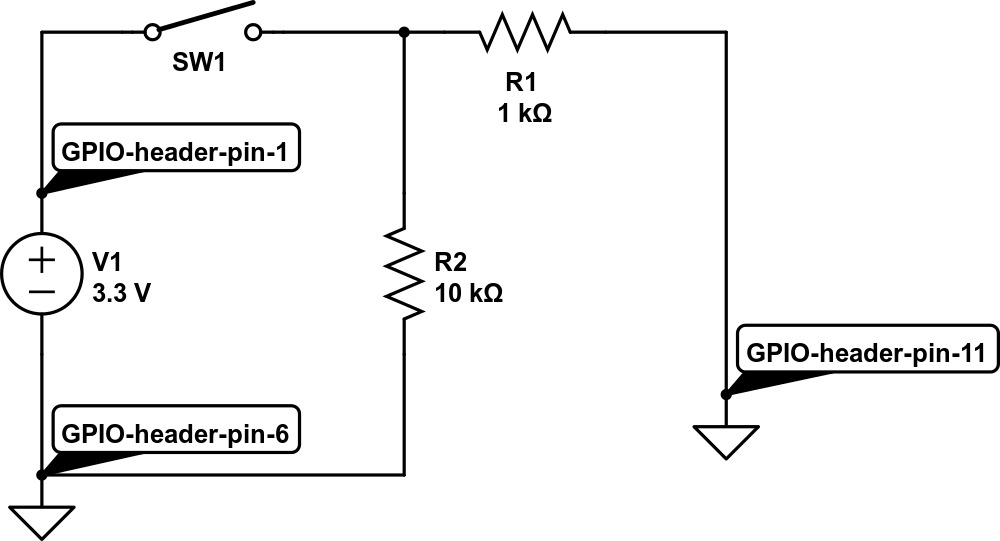
We connect the switch SW1 to the (always on) 3.3v supply (header pin
1), so that when the switch is in the on position it will supply the logical
high value. Resistor R1 prevents mishaps if we accidentally set header pin 11
to output at low (i.e. try to get the poor thing to pull the 3.3v supply to
0v, with unhappy consequences). Then we use a pull down resistor, R2, to
drag pin 11 low when the switch is open. When the switch is closed, R2 being
much higher than R1 implies that pin 11 will be pulled high by the 3.3v supply
from pin 1.
Confused? There's more explanation in the Embedded Linux tutorial linked above, and a much more detailed presentation at AdaFruit. (The latter is in relation to the Arduino but the principles are the same.)
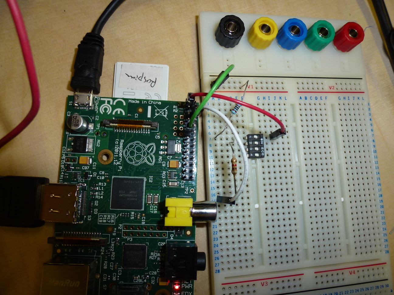
The breadboard to implement this circuit looks like this:
All we need now is some code to test what position the switch is in. We're sensing on header pin 11, which is WiringPi's 0, so we set 0 to input mode:
gpio mode 0 in
Now we can read the value like this:
gpio read 0
When the switch is on this will return a 1, and when it is off a 0. We're on a roll!9
2.4. Putting it Together: Sensor plus LED
We've nearly completed our lightening tour of the basics of interaction electronics with the Pi's GPIO facility. To finish off we'll connect up the sensing and responding sides of the picture. Here's a circuit which combines sensing from a switch with turning an LED on and off via software. The result is that we will now both sense from the switch and respond to the sensor data from software.
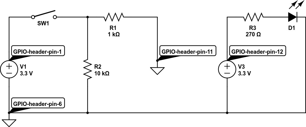
Nothing new here — we've just combined the LED driver circuit that we began with and the switch reader circuit from the previous section. Here we have the switch sensor to the left and the LED driver to the right.
The breadboard to implement this circuit looks like this:
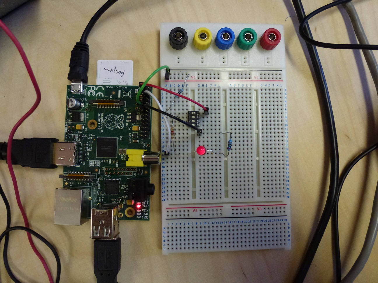
We've use a four-way switch (in "dual in line" or DIL
pin style) because we had one handy and because it was easy to connect to the
breadboard, but we're only using one of its channels — the equivalent of an
SPST or
"single pole single throw" switch.
The code to drive this uses some neat features of Unix shell script:
gpio mode 0 in
gpio mode 1 out

while :
do
  gpio write 1 `gpio read 0`
  sleep 1
done
The while : loop repeats forever (in shell ":" is a no-op command which always returns true, so the loop never hits a termination condition). We do this so that the program keeps testing to see if the switch position has changed. We don't really need to do this every few milliseconds, so to make the resultant load on the machine a little lower we use sleep to pause the program and set a wakeup timer in the operating system. The value of "1" passed to sleep means "one second", so our loop will run once per second, or thereabouts.10
The forward quotes (or backticks) in gpio write 1 `gpio read 0` do "command substitution": they run the command contained between the two quotes and replace the command with whatever is returned, then running the enclosing command. Here we're saying "read a value from GPIO 0" and then "write that value to GPIO 1". When the switch is on GPIO 0 will read high (and the command will return 1), at which point we'll write 1 to GPIO 1, our output pin which is driving the LED (so the LED will turn on). If the switch is off, then GPIO 0 will read low, returning 0 which will then be written to the output pin and turn the LED off.
2.5. Getting a Buzz Out of Trannies
We've done the let there be light! bit — how about making a noise to go with it? We'll finish up this part by hooking up buzzer to make an annoying whiney sound, partly because we'll need one of these later for our flood alarm project, and partly because it will introduce us to a new component, the transistor (or trannie in British English — North Americans please change your Google Translate preferences accordingly ☺).
Transistors are incredibly powerfull little gizmos, and their invention was one of the biggest steps in the history of solid state electronics, leading directly to the creation of integrated circuits (or silicon chips in the popular vernacular) and the whole miniaturisation feeding frenzy that the techy world has been enthralled by for the last half century or so.
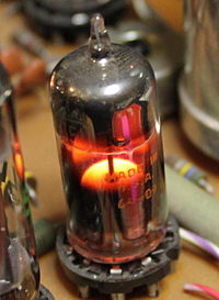
Transistors allow the rapid and efficient switching of a large flow of current using a much smaller flow. Amongst many other things this is the basis of the amplification that pretty much every hifi, TV, phone, MP3 player, etc. etc. uses to drive their loudspeakers. If it wasn't for transistors we'd all be carrying around car batteries and keeping nice and warm from the thermionic valves11 in our devices:
In the circuits above we've done our LED switching using the Pi's GPIO pins directly. These pins are only designed to deliver a very small current flow; if we want to drive a loudspeaker or a buzzer then we need more juice, and an easy and efficient way to supply it is to add a transistor to the mix. Our GPIO pin will still do the basic switching, but the transistor will mediate between GPIO and buzzer. Here's the circuit diagram:
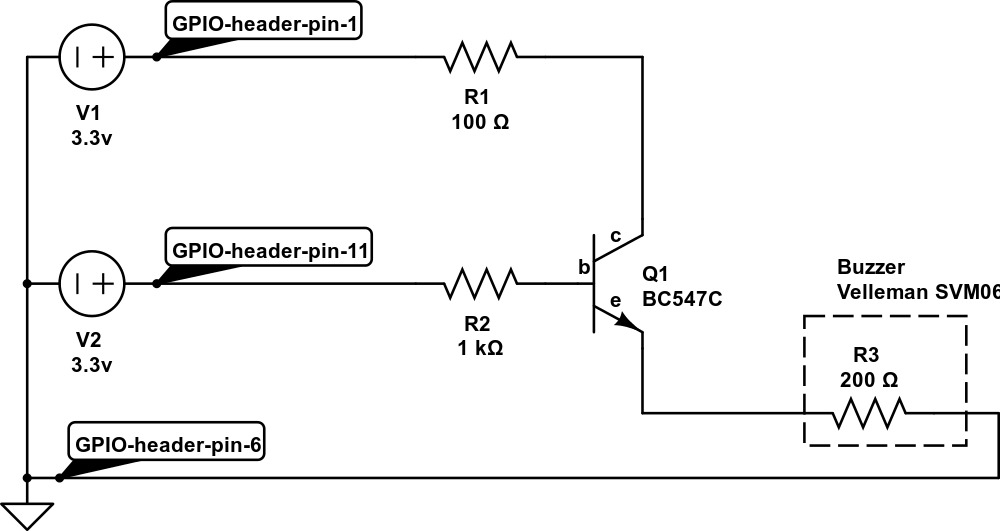
The transistor, Q1, has three pins, called base (b), collector (c) and emitter (e). When the base is set high (via GPIO header pin 11 in this case) the resistance between the collector and emitter is switched low. We place the buzzer in series with the transistor's collector/emitter pair and feed positive voltage through header pin 1. The effect is that the signal we send on header pin 11 (Wiring Pi's GPIO 0) will now turn the buzzer on or off.
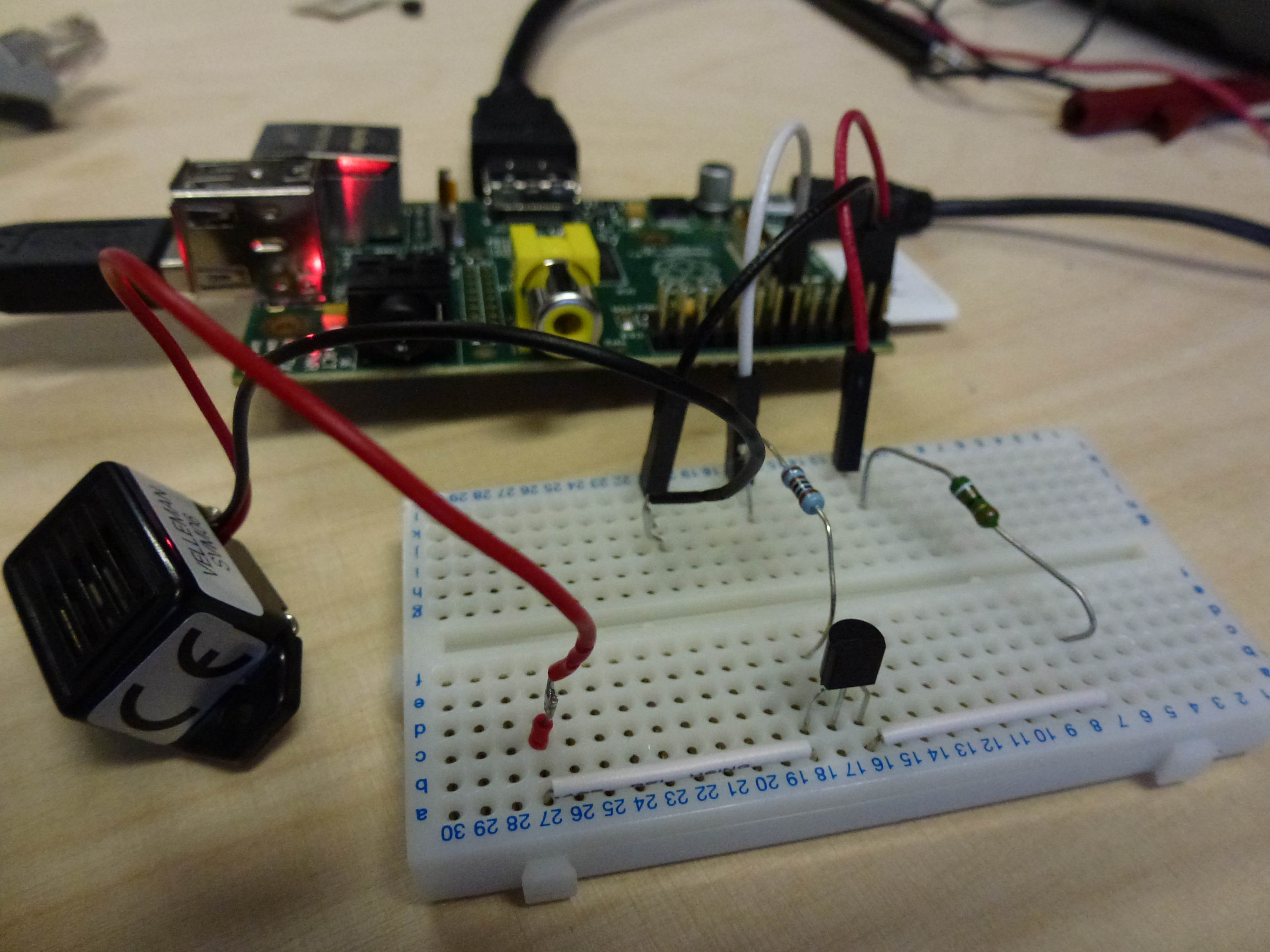
Here's the circuit wired up on our trusty breadboard:
Finally here's an example data sheet for a common transistor, if you're curious about the gorey details, for the BC549C transistor.
So we've now written programs on the Pi that can both sense from the outside world (e.g. the position of the switch) and send out a response (lighting or extinguishing an LED, or buzzing a buzzer). We've taken our first steps in interaction electronics; now its time to look at a couple of simple projects that we can build using the techniques that we've learned so far.
3. Parent Alarm
Parents — they're quite handy for doing the shopping and making breakfast and the like, but they do tend to get in the way, don't they? And even perfectly innocent teenage activities like building a particle accelerator in your bedroom can easily lead to awkward questions and family misunderstandings.
Let's use a Pi and a pressure mat to give an early warning of parental feet in the corridor.
Materials:
- bell wire or similar
- a pressure pad sensor
- a breadboard
- resistors (270Ω, 1kΩ, 10kΩ)
- green and red LEDs
- link wire
- jumper cables
- a multimeter (optional)
The first part is easy: we just replace the switch in the reading from switches circuit with a pressure mat12. Here's an example mat:

This works just like a switch — there are two wires to connect to, and when a heavy object (e.g. a parent) stands on the mat the two wires are connected (i.e. the resistance between them cycles between very high and very low).13 So we can use exactly the same circuit we used earlier for reading from a switch and turning an LED on or off:
One limitation of this circuit is that if Mum should happen to pop in one day and zap 50,000 volts across the Pi's GPIO pins the poor thing is unlikely to remain enthusiastic about driving our indicator LED — but we won't actually know that anything has changed, because as it stands there is no indication of normal operation as opposed to the various possible failure conditions. The next circuit addresses this limitation by adding another LED that is lit up when the pressure pad is not being stood on. That way we'll have an indicator of what state the system is in for both the "everything's ok" and the "run and hide!" conditions, so we'll immediately know if we've forgotten to switch the thing on, or if one of the LEDs has died, or etc.
The circuit:
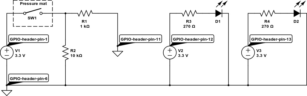
The breadboard for this circuit looks like this:
The green LED runs when the mat is not being stood on, indicating that all is fine; the yellow LED (red would also be a good colour) lights up when it's time to hide the particle accelerator and pretend to be doing the homework.
A closer look:
We need a new program to drive the extra LED (which is on Wiring Pi's GPIO 2, connected on physical header pin 13). In Unix shell script a suitable program is this:
gpio mode 0 in
gpio mode 1 out
gpio mode 2 out

while :
do
  if [ `gpio read 0` == 1 ]
  then
    gpio write 1 1
    gpio write 2 0
  else
    gpio write 1 0
    gpio write 2 1
  fi
  sleep 1
done
Here the two LEDs are controlled on GPIO 1 and 2, and as before we're reading
the input on GPIO 0. When someone stands on the pressure mat the input is 1,
and the first branch of the if statement will turn the first LED on and the
second one off; otherwise the reverse will happen. So of our two LEDs, one
will indicate safety and the other an alarm state.
Job done.
4. A Flood in the Basement
There's a poltergeist who lives in my basement. Either that, or I've had three completely coincidental pipe failures in the space of a couple of years. The last leak had such a high flow rate that if I hadn't wandered past in the morning and wondered what that hissing noise was we would have had a brand new swimming pool by the evening. The most worrying thing was that the leak came from a pipe joint that was brand new a year ago (and not fitted by me, either, but by a skilled professional14).
So I decided I needed a bit of long-term plumbing reassurance in the form of a water alarm that will send me an SMS text message whenever things get wetter than expected under the house. With a Pi and an alarm circuit like our parent alarm this turns out to be a nice project.
Materials used:
- as per the parent alarm, minus the pressure pad
- a simple mobile phone with USB cable, or a network-connection and an account on an SMS web service
The trick here is to find a way to sense the presence of moisture. As water conducts electricity we can do this using a variation on one of our switching circuits: we'll run a length of two-core wire through all the areas where we expect flooding and strip each core so that a flood would connect the two cores together.
To decide on the values for the circuit that we'll use to connect to the Pi,
we need to test the resistance of the water connections using a multimeter; it
turns out that we have something between 20k and 50k ohms when the bare wire
is immersed. When the wire is dry (hopefully the long-term average!) the
resistance will be infinite (like an open switch). We also should expect that
the wires may touch (if someone steps on them and presses them together, for
example), so we also have to cater for a 0 ohms resistance. To deal with these
possibilities we'll use a 1k limiting resistor and a 100k pull down resistor
like this:
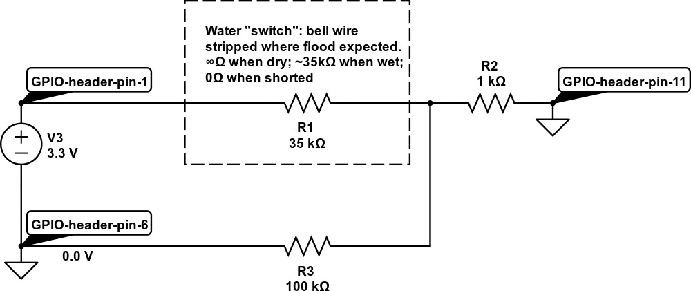
Here's what happens in our three cases:
- When the wire is dry, R1 acts as an infinite resistance, and pin 11 (which we set in input mode) is pulled low via R2 and R3.
- When the wire is wet, R1's resistance will be some way lower than that of R3 (the pull down resistor) and so pin 11 will be pulled high.
- If the wires are shorted R1's resistance will be close to zero, but we will not draw too much current from the Pi because of the presence of R2.
The code to read from our water sensor is very simple: gpio mode 0 in sets things up, and gpio read 0 takes a reading. When things get wet (or there's a short circuit) the read statement will return 1; otherwise it will return 0.
4.1. Hooking it all Together
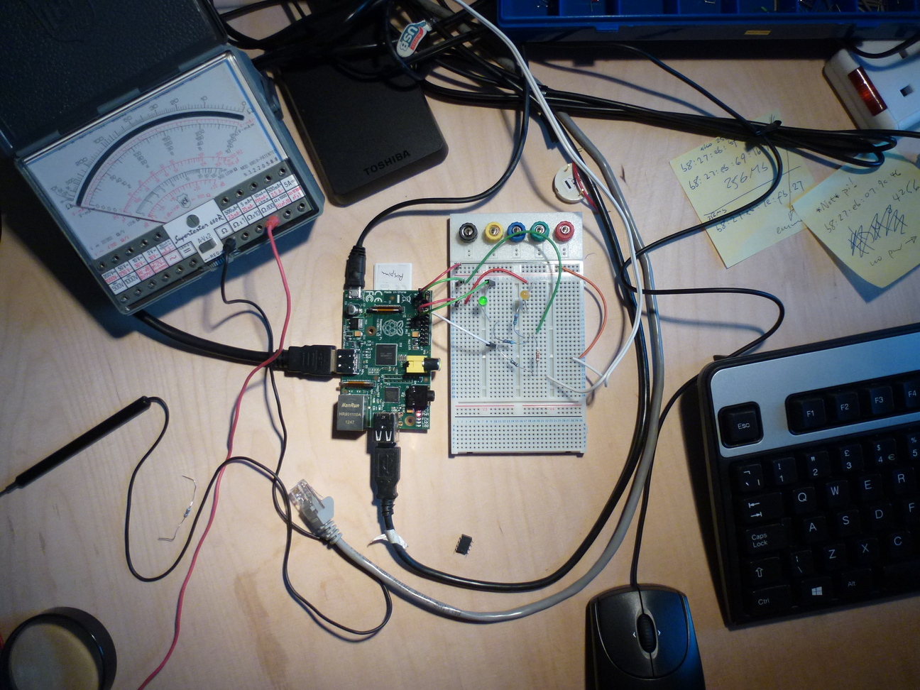
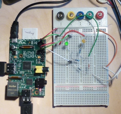
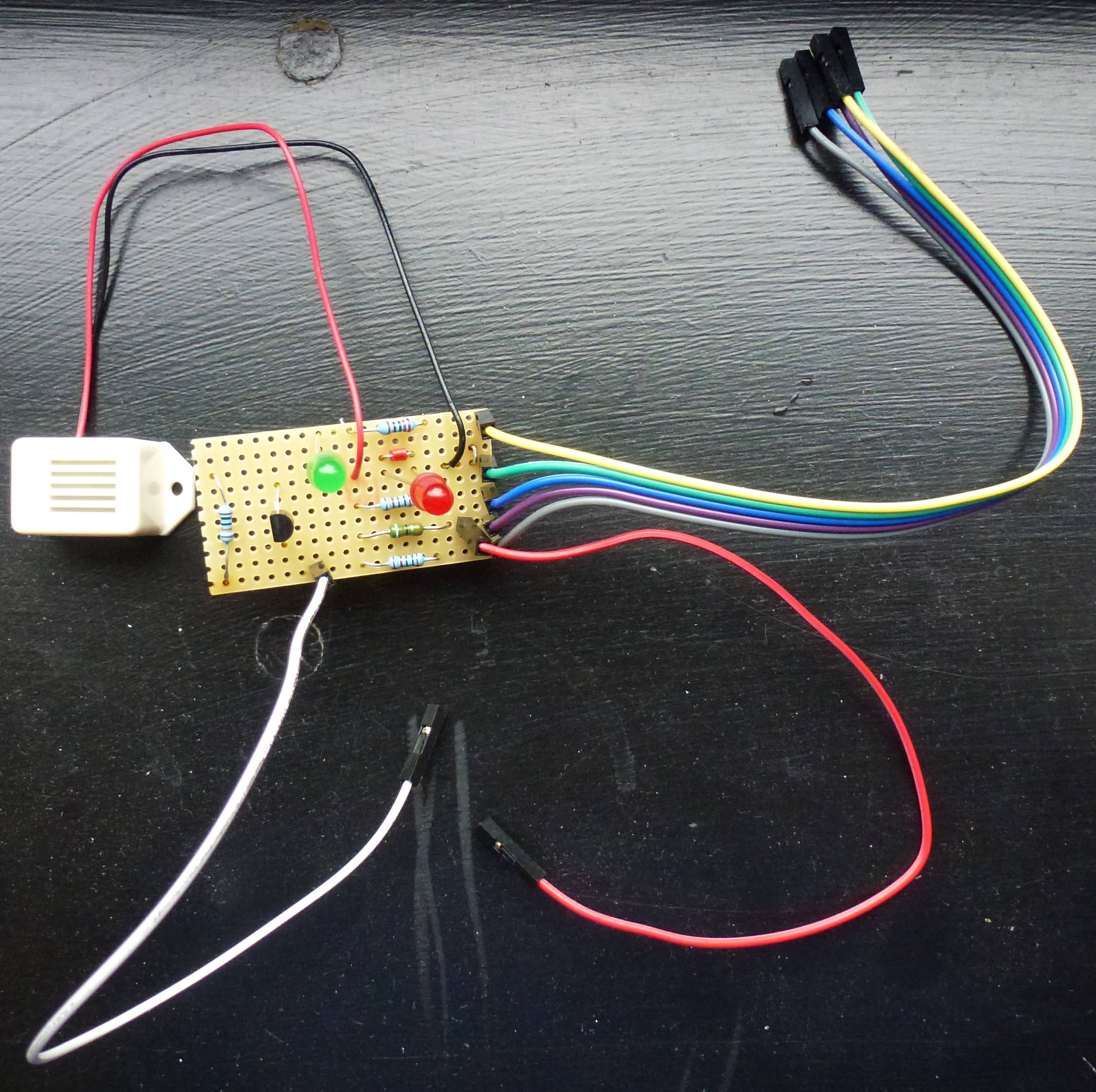
Finishing off the flood alarm is a matter of combining the LED and buzzer notification circuits with the water sensor just above. The breadboard looks like this:
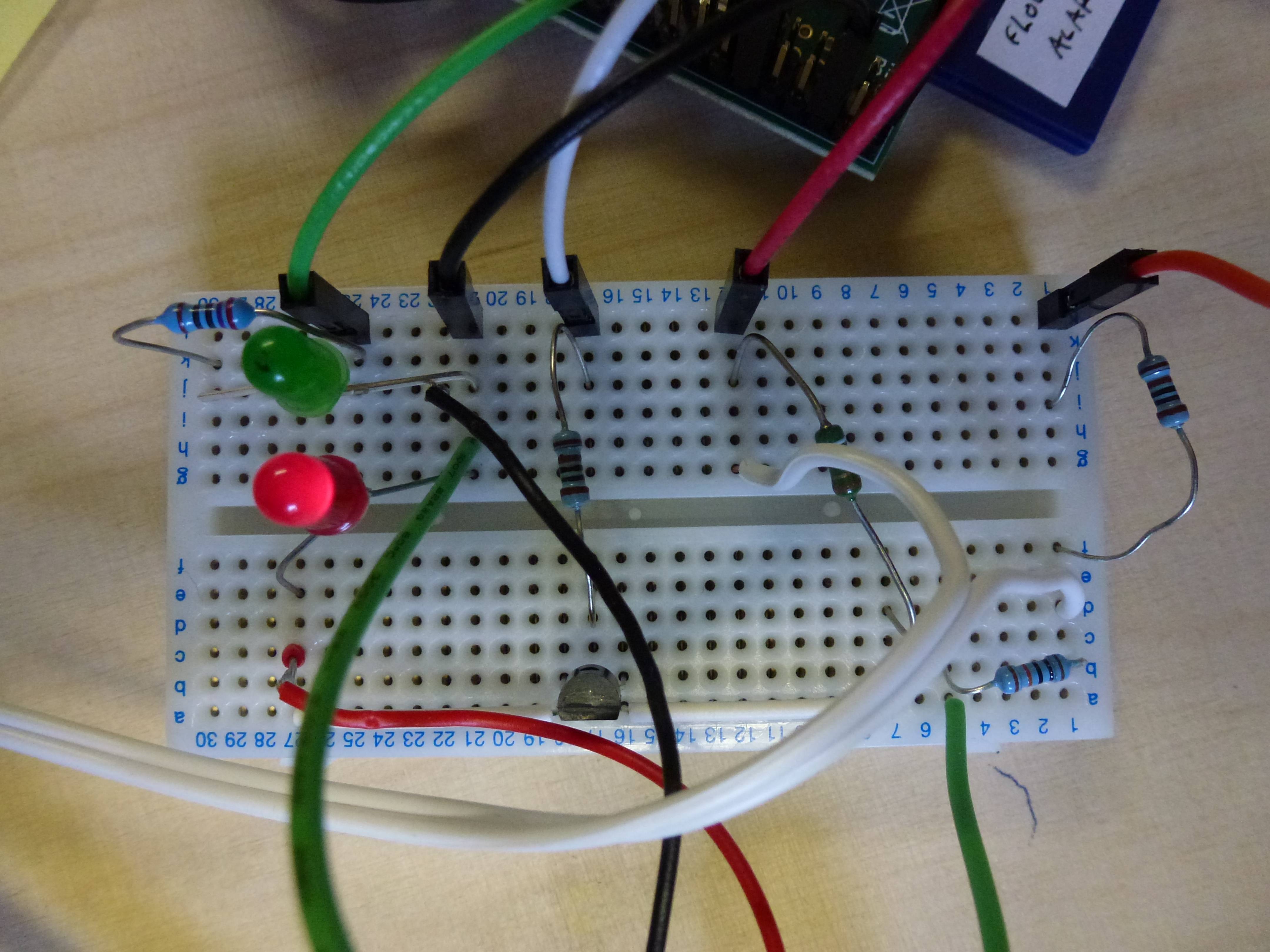
Here it is in context, with a fantastically expensive test rig consisting of a length of bell wire to dip in a plastic box full of wet stuff:
Here's the complete circuit diagram:
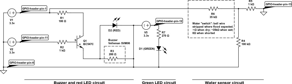
This combines the buzzer and LED driver circuits (one for the buzzer and red LED, using a transistor driver, and one for the green LED using GPIO alone) and the water sensor circuit. With a working and tested version running on the breadboard, we're all ready to build it, box it and install it!
4.2. Building and Installing
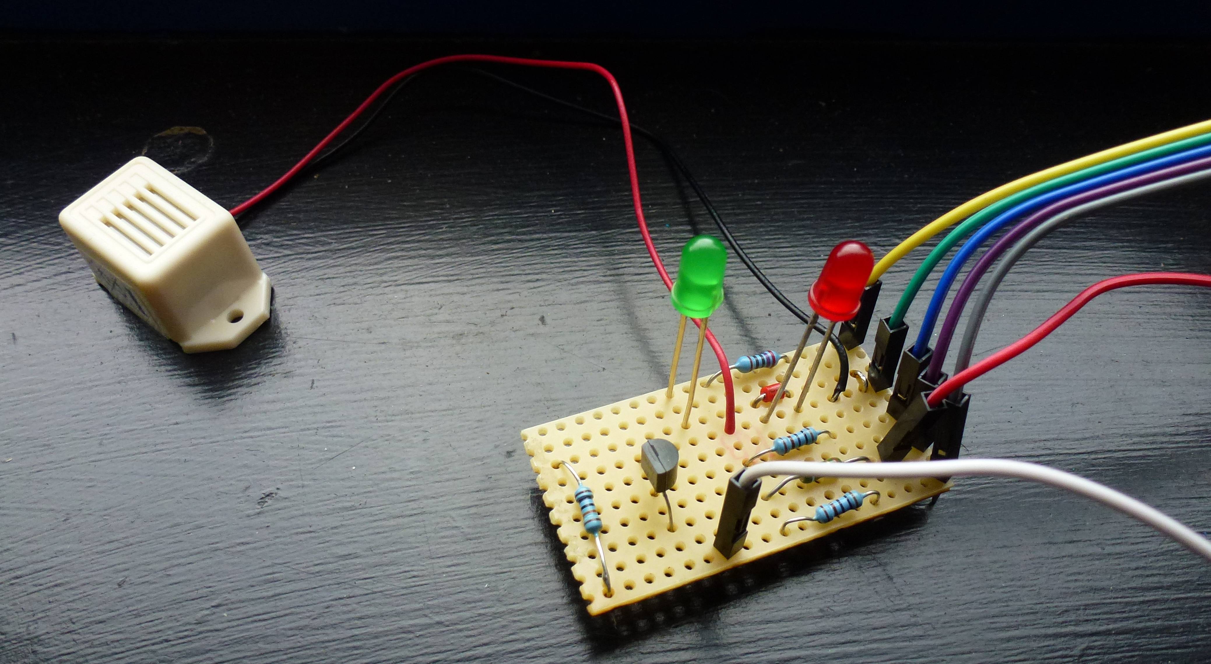
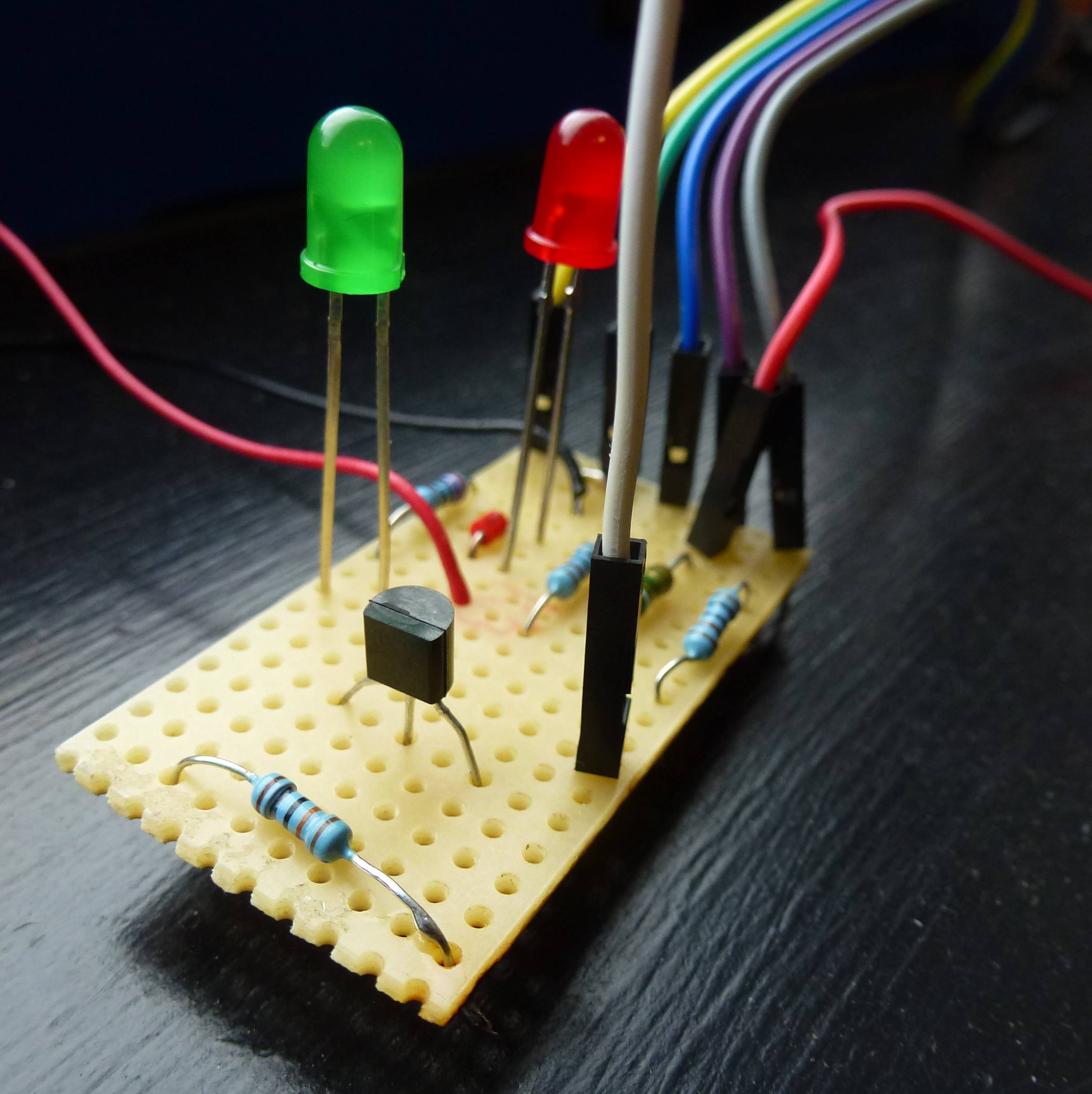
Now, I want my breadboard for other things, and I want to box up the beastie for installation in my basement, so the final step is to solder it all together onto a permanent fixture — in this case a piece of stripboard:
Stripboard is very like breadboard in layout, with a sequence of conductive strips on the underneath of the board:
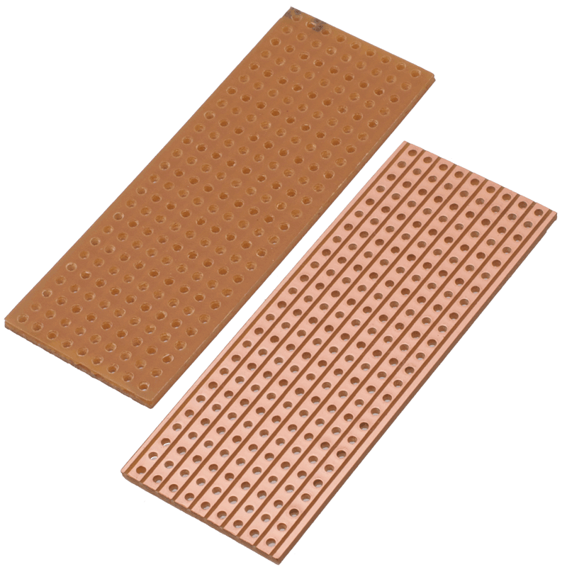
If we need to we can make breaks in the strips, which I did underneath the row of resistors that you can see at the left-hand end of the board here:
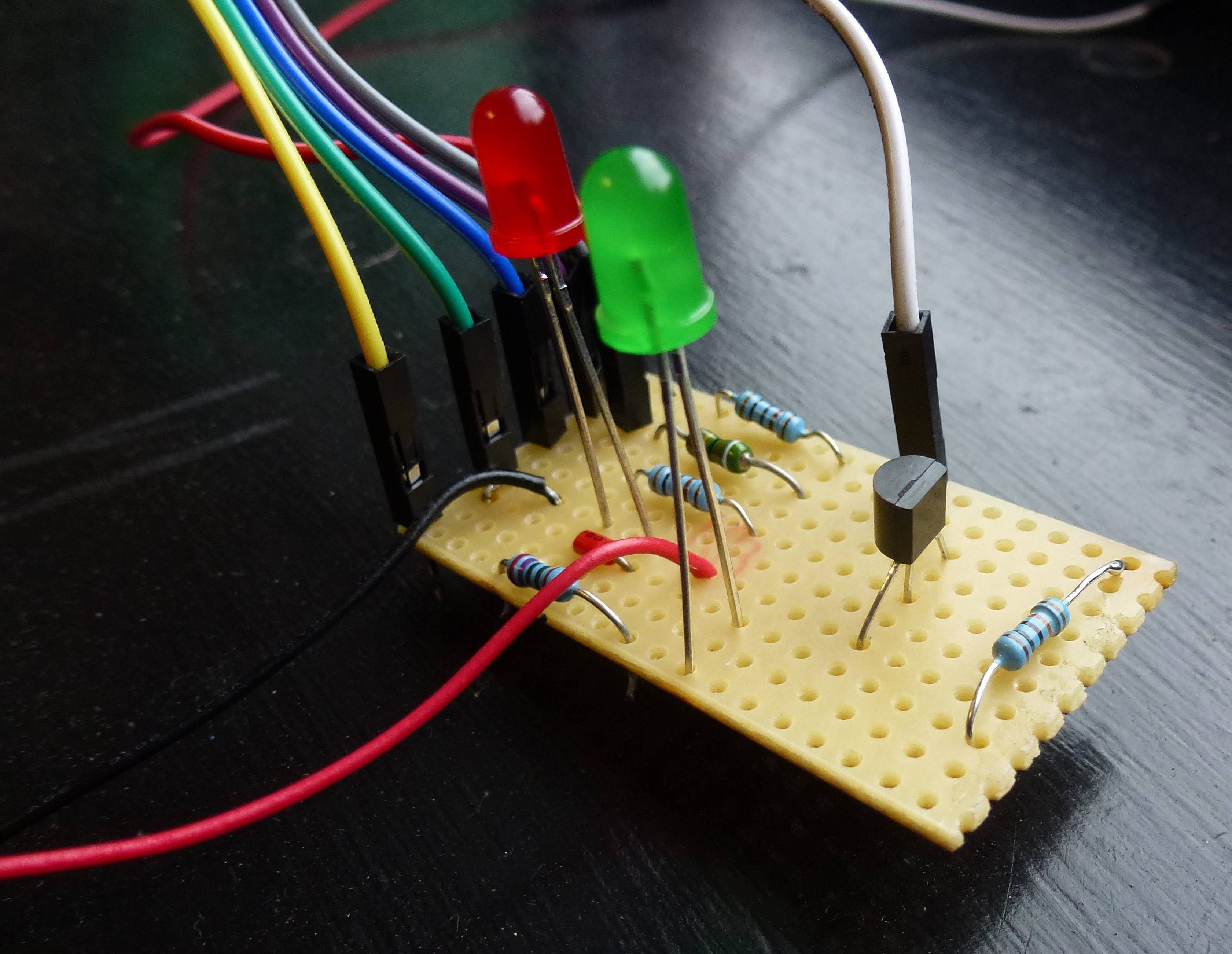
And here it is from the reverse angle:
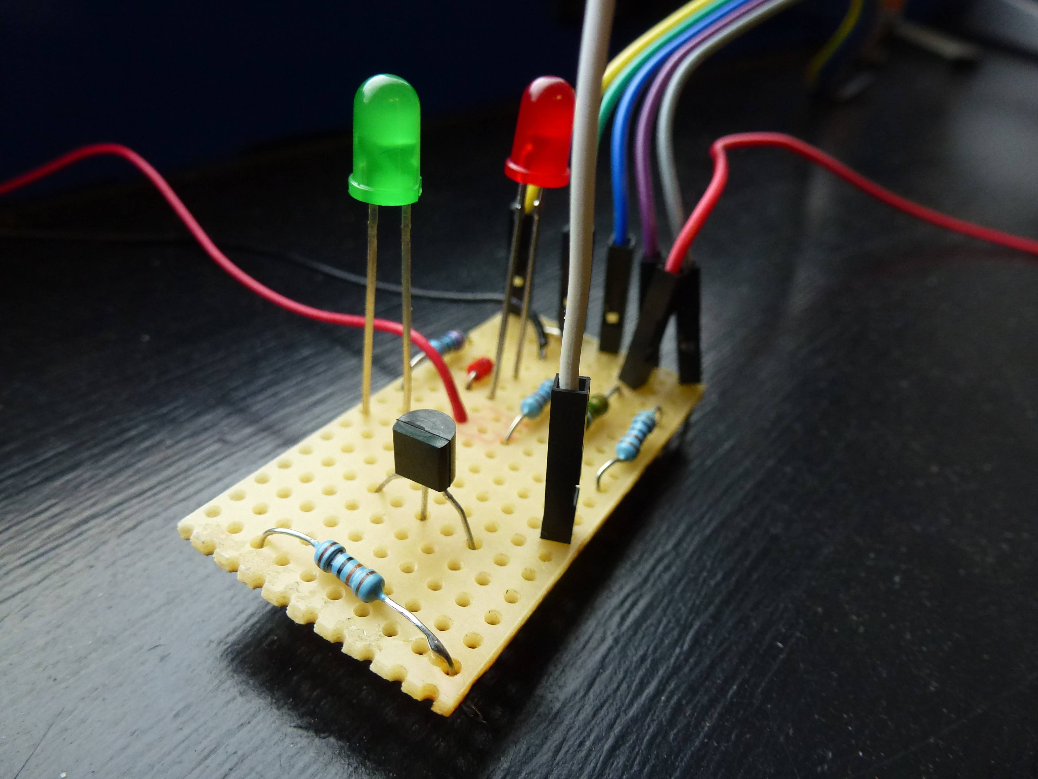
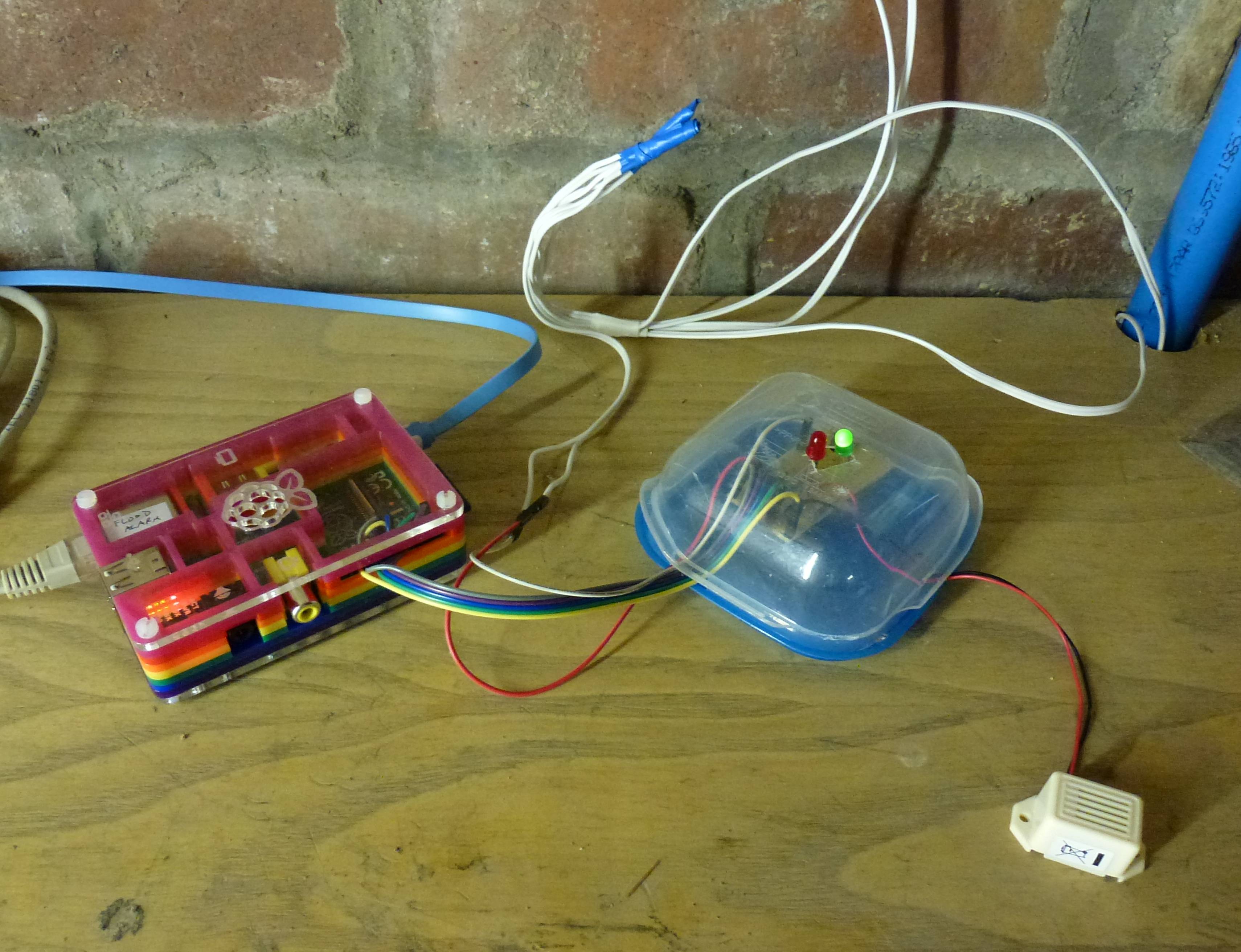
Here is the complete build, all ready for installation:
4.2.1. The Software
The software for the beast is a bit more complex than we've worked with before — it loops forever and takes care of sending an SMS notification when it senses a flood, but it also does some standard shell magic like processing command-line options, giving help messages and the like. To prevent too many messages, when it finds a flood that doesn't go away it also waits progressively longer periods before testing again.
Here's the code:
#!/usr/bin/env bash
# flood-alarm.sh

# standard locals
alias cd='builtin cd'
P="$0"
USAGE="`basename ${P}` [-h(elp)] [-w(et)] [-d(ry)]\n
\twet and dry are for testing; normally we are run without options\n
\tand loop forever waiting for state changes on GPIO 2..."
OPTIONSTRING=hwd

# specific locals
WET=0
DRY=0
STATUS=none
pdate() { date '+%b %d %Y %T'; }

# message & exit if exit num present
usage() { echo -e Usage: $USAGE; [ ! -z "$1" ] && exit $1; }

# process options
while getopts $OPTIONSTRING OPTION
do
  case $OPTION in
    h)	usage 0 ;;
    d)	DRY=1; WET=0 ;;
    w)	WET=1; DRY=0 ;;
    *)	usage 1 ;;
  esac
done
shift `expr $OPTIND - 1`

# get started
echo
echo ========================================================================
echo Hello! no flooding today, we hope...
pdate
echo

# set up the gpio pins
gpio mode 0 out # pin 0 is the buzzer and red led
gpio mode 1 out # pin 1 is the green led
gpio mode 2 in  # pin 2 is the water sensing circuit

# helpers for processing state changes
statusDry() {
  if [ $STATUS == wet ]
  then
    echo Becoming dry at `pdate`...
  else
    echo Staying dry at `pdate`...
  fi
  STATUS=dry
  gpio write 0 0
  gpio write 1 1
}
statusWet() {
  if [ $STATUS == dry ]
  then
    echo Eek! Becoming wet! `pdate`
  else
    echo Bugger. Staying wet! `pdate`
  fi
  STATUS=wet
  gpio write 0 1
  gpio write 1 0
}

# helper to send notifications when wetness persists
notifyFlooding() {
  DATE_TIME=`date '+%b %d %Y %T'`

  # send an SMS over the net
  PW=`cat flood-alarm-data-secure-store/bulksms.txt`
  SMS_STATUS=`./hc-sendbulksms.sh -u hcunningham \
    -p "${PW}" -n 447712341234 -m "Flooding in the basement? $DATE_TIME"`
  echo "BulkSMS says: ${SMS_STATUS}"

  # we could also use our NotiPi code here to send an SMS over the phone...
}

# either do a state change (for debugging), or loop
if [ $DRY == 1 ]
then
  statusDry
elif [ $WET == 1 ]
then
  statusWet
else
  # after an alarm wait at least 30 mins before re-testing
  MIN_DELAY=30
  DELAY=${MIN_DELAY}
  while :
  do
    WET=`gpio read 2`
    if [ $WET == 0 ]
    then
      statusDry
      DELAY=${MIN_DELAY}
      sleep 1
    else
      # wait a little and test again, just to be sure
      sleep 3
      WET=`gpio read 2`
      [ $WET == 0 ] && echo 'Hmmm... false alarm!' && statusDry && continue

      # raise the alarm
      statusWet
      notifyFlooding
      echo Taking a break for ${DELAY} minutes...
      sleep ${DELAY}m

      # if it is still wet we want to sleep longer next time
      DELAY=`expr 2 \* ${DELAY}`
      if [ $DELAY -gt 1440 ]
      then
        # max delay is 24 hours
        DELAY=1440
      fi
    fi
  done
fi
And it works!
Almost.
It worked fine in the office, but when I wired it up in the basement I started getting false triggers. This seemed to be an effect of the cable runs that I chose — whereas my initial test rig was just one long length of wire, I initially attached four separate runs in the basement, to cover joints on two of the pipes that had leaked previously and also two floor locations where water collects when there's flooding. Here's an example of the former:
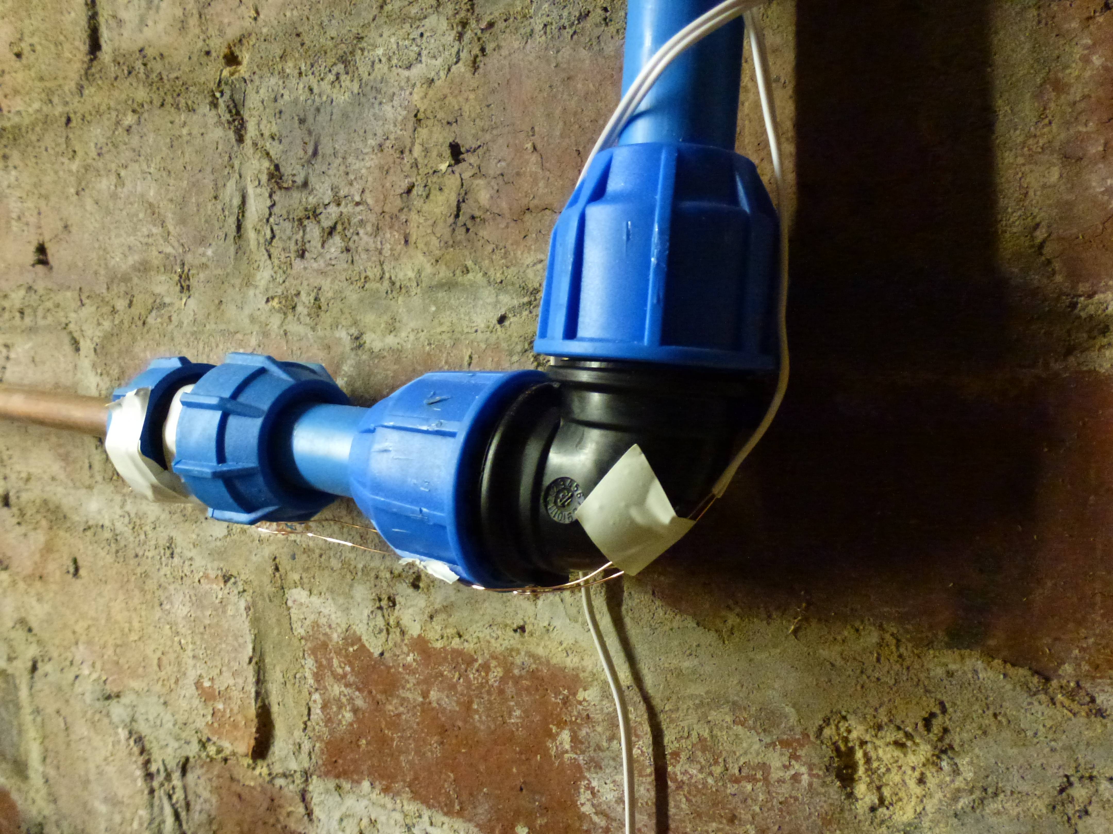
The separate cable runs were then joined by twisting the wires together, like this:
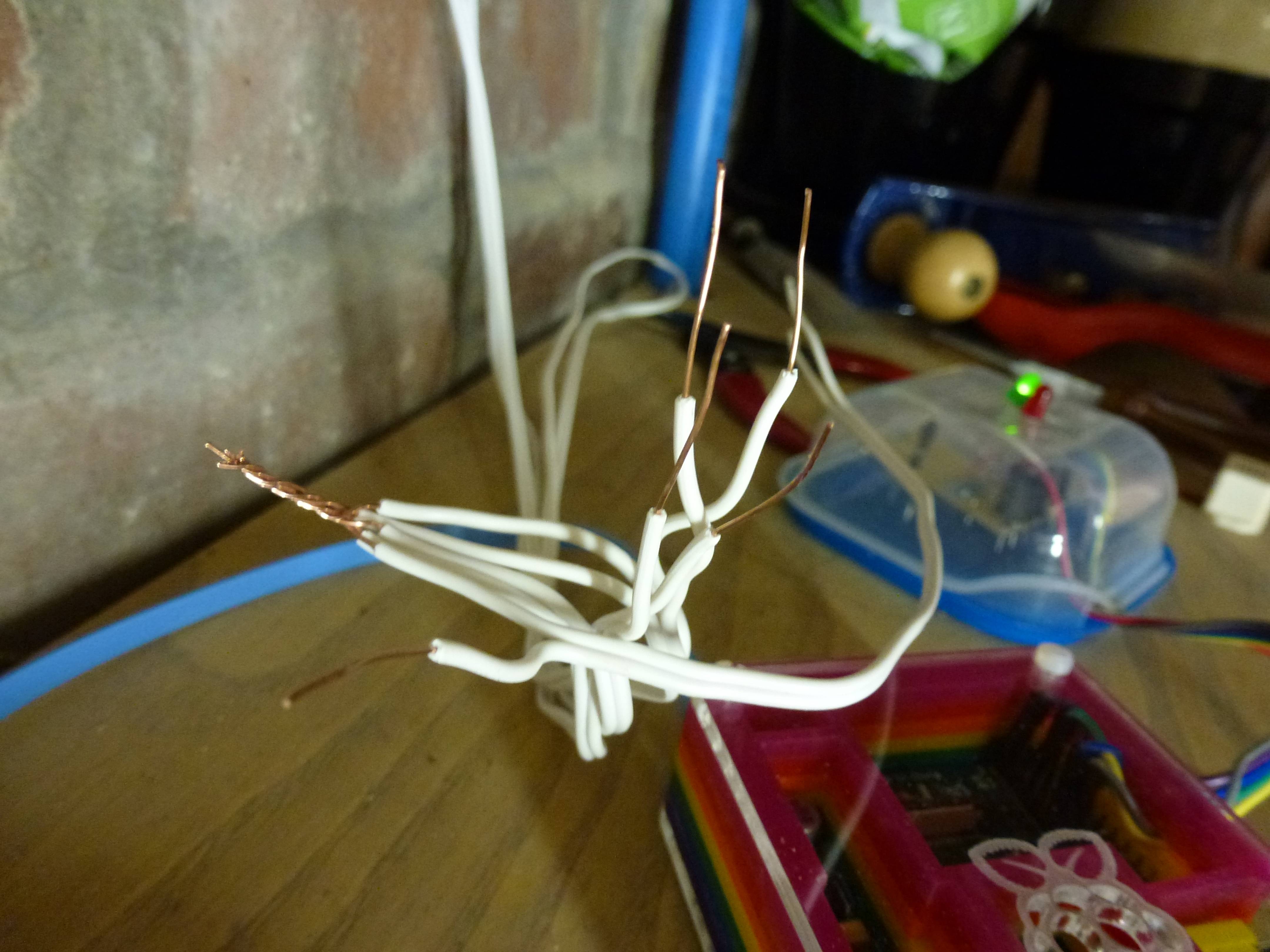
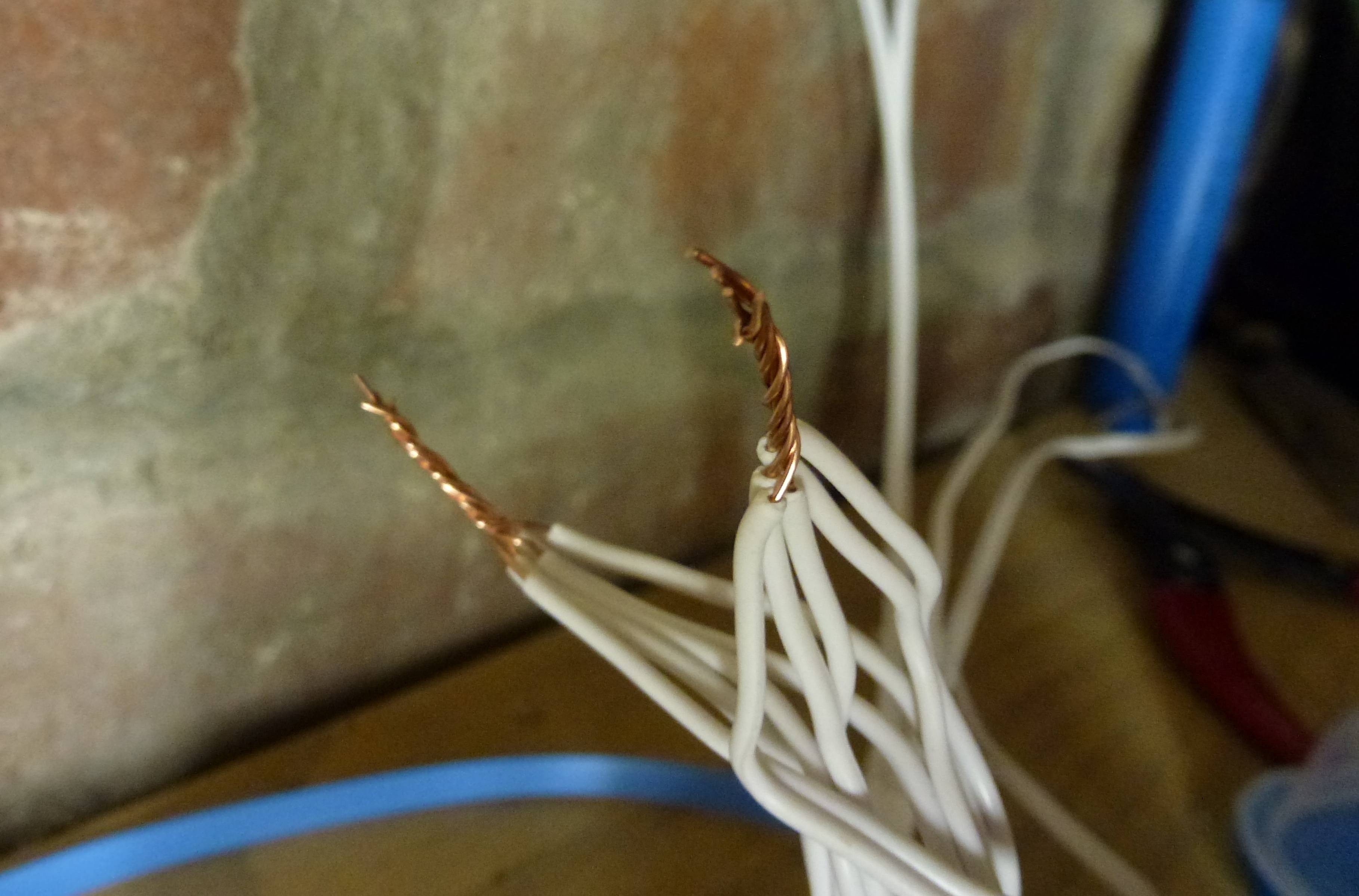
This arrangement created a level of capacitance in the wiring rig that was, over time, enough to trigger the GPIO pin in reading state. After a few seconds, it would trigger. To fix the problem, I did two things:
- reduced the capacitance by using a different jointing method (a mini-breadboard), and removing one of the wire runs
- added a software delay of three seconds before raising an alarm
The latter appears in the script above and looks like this:
      sleep 3
      WET=`gpio read 2`
      [ $WET == 0 ] && echo 'Hmmm... false alarm!' && statusDry && continue
This code branch is followed whenever we get a "wet" reading, and says "first
sleep for 3 seconds, then test the indication again". When we find that the
wet reading has gone away we treat it as a false alarm and continue waiting
for a new reading.
A couple of other wrinkles: the alarm Pi has no monitor attached, so we need to set this going with nohup to prevent the process dying when we log out. To be precise:
nohup bash -c "`pwd`/flood-alarm.sh &"The output from the script is then collected in nohup.out and we can watch new entries being written like this:
tail -f nohup.outFinally, the local network is protected by a firewall and network address translation in our broadband router. To allow us to log in when not at home, I used the excellent PageKite system to forward Open SSH traffic to the Pi running the alarm system. (If you don't know SSH, time to find out — it is an essential tool for secure communication to your Pi-based systems (and others).15)
And that's it. Now I can sleep easy... until my phone gets a text, that is!
5. Books and Resources
5.1. Software and Source Code
Packaged versions of some of the projects (e.g. the SimBaMon battery monitor) is available from https://launchpad.net/~hamish-dcs/+archive/pi-gate (an Ubuntu PPA16 set up to be suitable for Raspbian). See the next section for installation instructions.
Source code for all the projects is available on the Git Hub open source hosting site. The project is called Pi-Tronics. To get started install git and clone the master branch:
git clone git://github.com/hamishcunningham/pi-tronics.gitThis will create a directory pi-tronics on your local system. See the file README.txt in that directory for details of what is where.
You can also browse the code on-line — here's the flood alarm script, for example.
5.1.1. Installing Pi-GATE Software
To install from our Ubuntu personal archive:
1. Add this line to /etc/apt/sources.list:
deb http://ppa.launchpad.net/hamish-dcs/pi-gate/ubuntu precise mainYou can use a text editor (e.g. nano) to do this, or paste this one-liner into a terminal prompt:
echo deb http://ppa.launchpad.net/hamish-dcs/pi-gate/ubuntu precise main |sudo tee -a /etc/apt/sources.list2. Import the GPG encryption key from Ubuntu so that the Pi can verify the package's validity:
sudo apt-key adv --recv-keys --keyserver keyserver.ubuntu.com --recv-key 6C12C1CF3. Update your list of available packages (this may take a couple of minutes):
sudo apt-get update4. Install the package (where "package-name" is one of our packages, e.g. "simbamond" for the battery monitor):
sudo apt-get install package-nameAnd that's it!
Note: the above gets you the most recent stable release; if you want to live on the edge, you can get more recent experimental builds by adding the snapshot PPA to your sources list, e.g.:
echo deb http://ppa.launchpad.net/hamish-dcs/pi-gate-snapshots/ubuntu precise main |sudo tee -a /etc/apt/sources.list
5.1.2. Installing WiringPi for Raspbian
On Raspbian, you can install WiringPi from a .deb file like this:
  wget https://raw.github.com/hamishcunningham/wiringpi/master/package/2.13/unstable/wiringpi_2.13_armhf.deb
  sudo dpkg -i ./wiringpi_2.13_armhf.deb
See our page on Pi software packaging for more details.
5.2. Books and Sites about the Pi
Books about the Pi are proliferating almost as rapidly as the community of Pi aficionados.17 These are three of my favourites:
- Eben Upton and Gareth Halfacree's book The Raspberry Pi User Guide is definitely the first place to start. Required reading.
- Gray Girling's Haynes manual is my all-time favourite so far, perhaps because I remember my brother using these manuals to figure out how to fix his Triumph Herald way back when. It also has great graphics and an excellent mix of hardware and software, plus some philosophy and history to boot. I love it.
- Slightly off the beaten track, but a great fit for the Pi's mischievous implications, I recommend Stefan Sjogelid's Raspberry Pi for Secret Agents. If the NSA and GCHQ are going to spy on every citizen for no good reason shouldn't we spy on them in return?!
If it's your birthday, ask for a book token — there's more to drool over in the next section.
There are also lots of great websites about the Pi — some that stand out:
- The Pi foundation's site is the place to start: lots of good reference material, and there's always something new to read on the blog. For discussion and advice, the community forums are excellent.
- Cambridge Univerity Computer Lab is where the original idea for the Pi came from, and they host a great set of Pi materials including these tutorials.
- The MagPi monthly eZine is well worth a look, as is the Pi Weekly email news digest.
- The WiringPi library site is also well worth a visit.
There are oodles and oodles of Pi hobby sites — really too many to make a list these days!
5.3. Electronics Books and Sites
For introductions to basic circuit building, breadboarding or soldering, and to hacker electronics in general, see for example:
- Simon Monk's 2013 book Hacking Electronics, which achieves a nice balance between explaining relevant theory and quickly getting on with practical stuff right from the start. Although some of the chapters are specific to the Arduino18 there's a lot of generally useful stuff too, including introductions to breadboarding, stripboard, soldering and the like. A good book if you're in a hurry.
- The 2009 Make Electronics by Charles Platt, which also has loads of great introductory material, and is a typically high quality O'Reilly production with Make Magazine's usual emphasis on colourful graphics and detailed instructions for the hobbyist. This book is very detailed and has lots of intriguing background19.
- The Embedded Linux wiki has great globs of Pi-related stuff, including a bunch of very useful tutorials.
- AdaFruit's tutorial pages include an excellent guide to soldering (and one for measuring).
- Another useful beginners' site is Electronics Club.
And lots and lots of others!20
5.4. Circuits: Calculators, Simulators, Diagrams
The circuit diagrams are available on Circuit Lab under the Creative Commons BY-NC-SA licence.
For circuit debugging these Voltage/Resistance/Current calculators are useful: this one, this one, and this one all worked well for me at one time or another.
6. Warning!

Although all the voltages we're working with here are too small to hurt a big lump of a thing like a human being, it is perfectly possible to destroy your Pi by making connections to the wrong pins! It is also theoretically possible to create enough heat to start a fire (probably only if you pile something extremely flammable on top of it all and wait a week or so, but nevertheless please be warned).
The Pi has very low power consumption, but if you're an electronics newcomer (or even just dopey and error-prone like me) the safe thing to do is always power down whenever you're not working on your rig. And to proceed with caution!
Soldering brings with it its own set of potential gotchas of course. There's a clue to this in the involvement of a hot iron, molten metal and heated wires — we leave it as an exercise for the reader as to what happens when you touch something really hot with a part of your anatomy. If in doubt, don't try this at home.
Finally, please note that it is quite possible that these paragraphs contain nuts. Why don't sharks eat lawyers? Professional courtesy.
Footnotes
- To be picky, the Pi's default operating system's full title would be the Raspbian distribution of Debian GNU Linux.
- LED: Light Emitting Diode.
- 'Hello world!' is by convention the first program we write in a new language or for a new device.
- Gordon Henderson gives a good presentation of how to do this in his GPIO examples pages.
- Circuit diagrams were drawn and debugged using the excellent CircuitLab.
- This product may contain (or have been written by) nuts.
- Bet you didn't know the logo incorporates a 3D buckyball. Like I know what one is21. Please don't tell my old chemistry teacher. Mind you, that was back in the early 1930s, so buckyballs may not have been invented then. At lunch time we used to go and suck on a piece of coal to take the hunger pangs off.
- Note that we represent GPIO pins that are in input mode as ground in the diagrams — strictly speaking this is inaccurate, but it does allow us to run simulations on the circuits in CircuitLab. If you know a better way please let me know!
- If your head is hurting, try slapping yourself sharply in the face three times22.
- The exact length of time before the wakeup call comes is dependent on what else the machine is doing at the time.
- You can still see valves — or vacuum tubes — in action in some music kit. One reason for this is that when they're driven hard they distort an analogue music signal in interesting ways — that's the origin of the "fuzz box" guitar effect, or Jimmy Hendrix's entire sound repertoire, or etc.
- Note: don't position this mat or the wires connecting to it anywhere that someone is likely to trip over it. See also this warning. May contain nuts.
- This type of thing is commonly used in burglar alarm circuits.
- And not one called Harry Tuttle.
- And make sure you change your Pi's password to something fiendish before putting it on a network!
- PPA: Personal Package Archive. Usually used for Ubuntu software packages but also useful for certain types of packages for the Raspberry Pi.
- In July 2013 Google lists more than 12 million hits for the phrase "raspberry pi"!
- The Arduino is an extremely capable device that is both fore-runner and partner to the Pi. Based on a micro-controller chip, Arduino has been a major driver of the wave of low cost, flexible and open hardware on whose crest the Pi is now riding. It has a larger set of interaction functions (higher power and better safeguarded than on the Pi), but is a bit less powerful and general-purpose from a computational point-of-view. No doubt both will co-exist, and a good number of projects combining them are already available.
- I never knew, for example, that in terms of the movement of electrons electricity flows backwards from negative to positive, and that the conventional reverse flow is just that — a convention dating back to a mistaken conjecture by Benjamin Franklin. Well I never!
- If you really want to get in deep, here are two comprehensive sources: All About Circuits; the MIT Circuits and Electronics starter course in electrical engineering.
- And to think I work just round the corner from the Kroto institute. Shame on me.
- This probably won't help, but it will be amusing for anyone who's watching.