Last time I introduced everyone to the AirPi, an open environmental sensor platform. They provide a list of components, schematics, and software for you to build a rather tiny Pi sized weather station. I went through the process of ordering the parts and bread-boarding it up before. They also, however, provide everything in a convenient ready-to-solder kit, which is what I'll be writing about today.
Hamish went over to Cambridge for CamJam, the local RaspberryJam they've got over there. He had the chance to meet with some interesting folks, including Tom Hartley, one of the AirPi developers. He also picked up one of those kits so that I had something new to play with while some data records on my breadboard system.
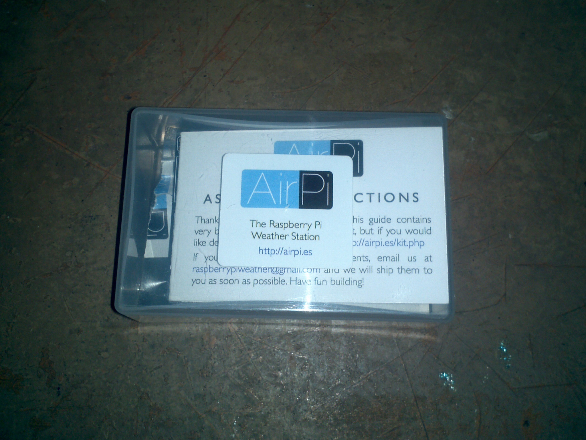 Kitbox
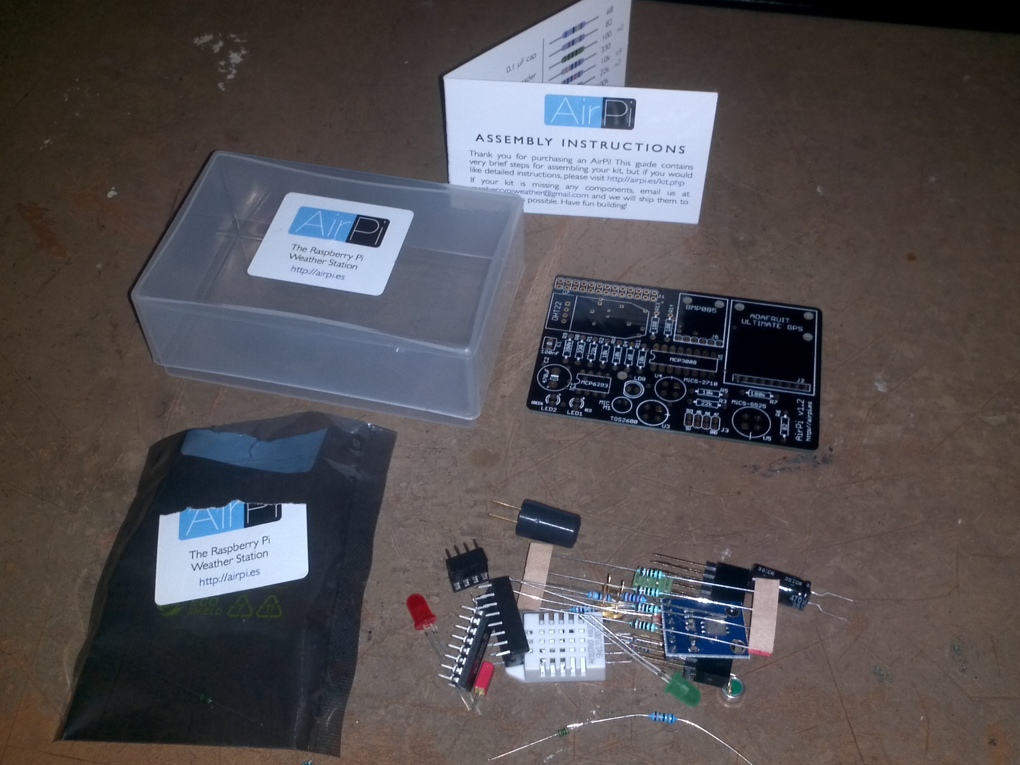 And all the stuff in it
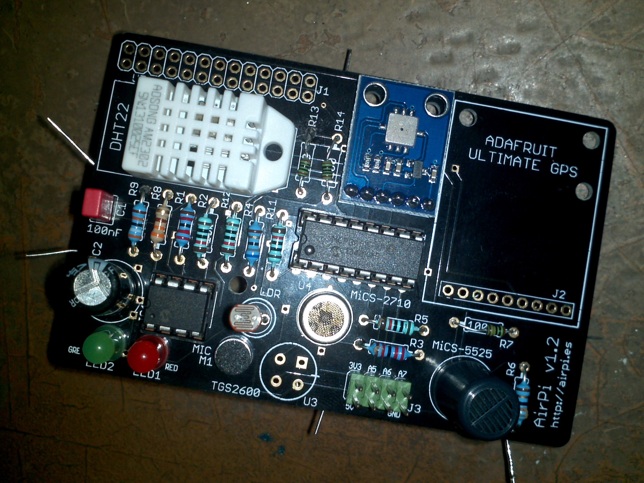
The first thing to know is that this is AirPi v1.2. This isn't what the directions on the site are currently for. This is a newer hardware revision, with a slightly different load-out. The primary difference is that the UV sensor has been replaced with a microphone. I'm not too sure about this change, but it means that the CA314 op-amp has been replaced with a MCP6283.
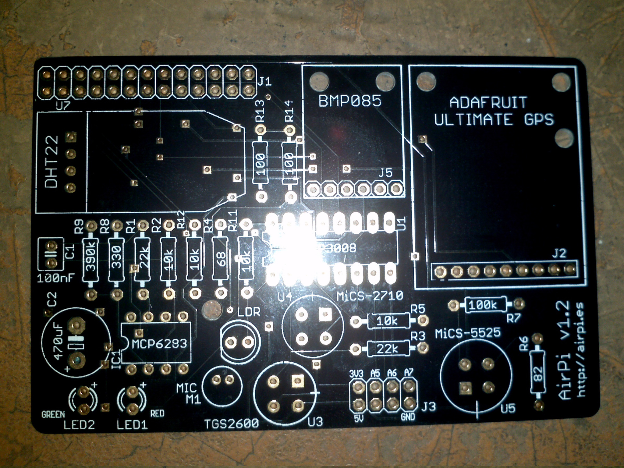 PCB top
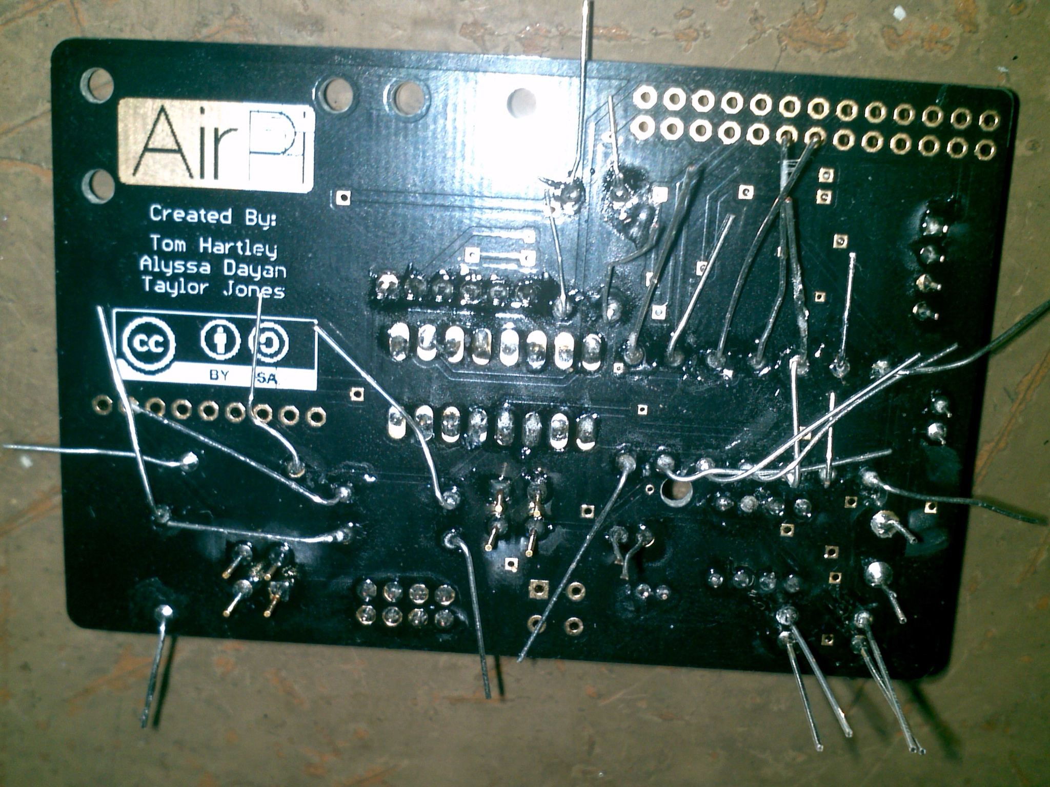
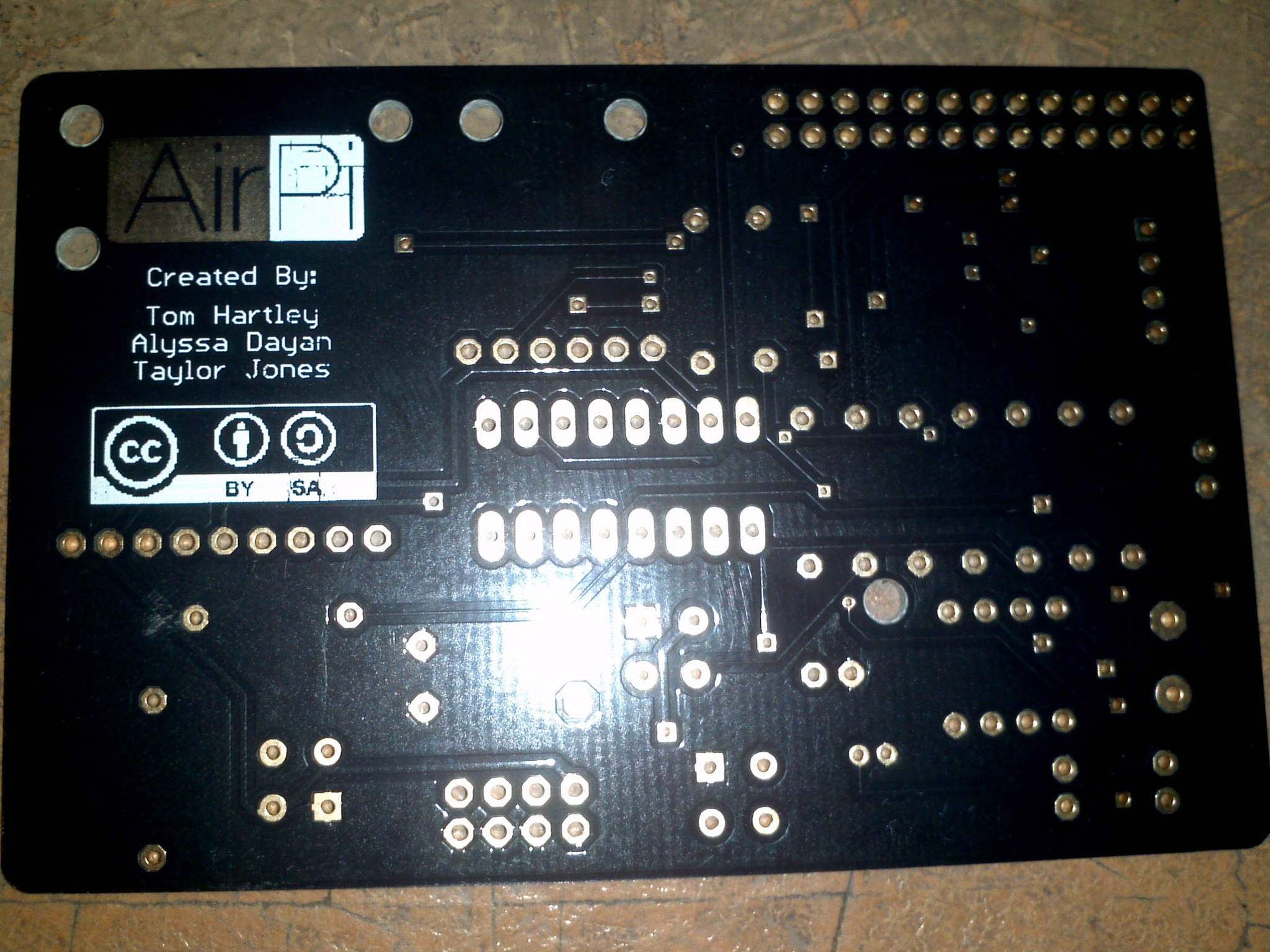 PCB bottom
You can also see there on the PCB spots for two LEDs (LED1 and LED2). These aren't new hardware per-say, they just may be new to you. The LEDs are included in the assembly directions, I simply didn't include them as I didn't feel the need for more blinking lights on the Pi. It's customisable hardware after all—gotta take advantage of that! The AirPi does itself. The kit comes with the separate MICS-2710 (NO2) and MICS-5525 (CO) sensors, which I couldn't get for my breadboard.
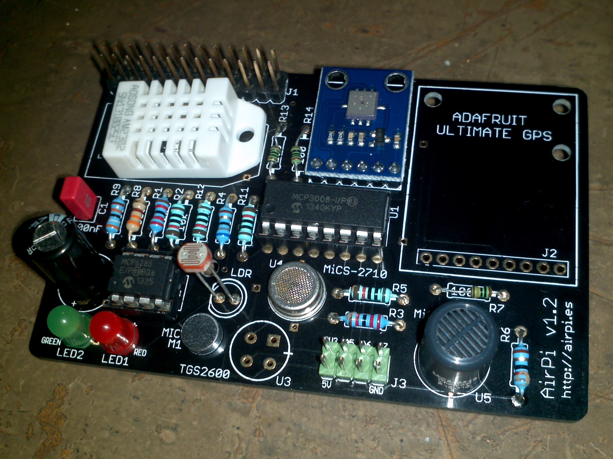
 Just about everything soldered on
 You can see where the board has melted some
This took me about an hour and a half to do. The only thing that's not soldered yet is the connector for the Pi. I was very involved in actually sorting everything out though that I forgot to take more pictures of the process. It's like following a set of LEGO directions so from that point of view it's easy. The catch is that soldering is sometimes hard. Which, as I've pointed out above, has led to me melting the board a little in some places, and odd shaped blobs of solder in others.
You can see on the PCB the empty TGS2600 location, which is fine as it's been replaced with the MICS sensors. You can also see one resistor of a different color. That's because somehow, probably sometime between the kit being made and me getting it, a 330Ω resistor was lost. Fortunately my trusty Maplin kit of resistors saves the day, but I must say that working out which resistor was which was the hardest part of doing this kit. The colors on the printed card are hard to distinguish, and it's hard to distinguish them on the resistors themselves. Impossible on the tiny little ones, like the 100Ω and 100KΩ.
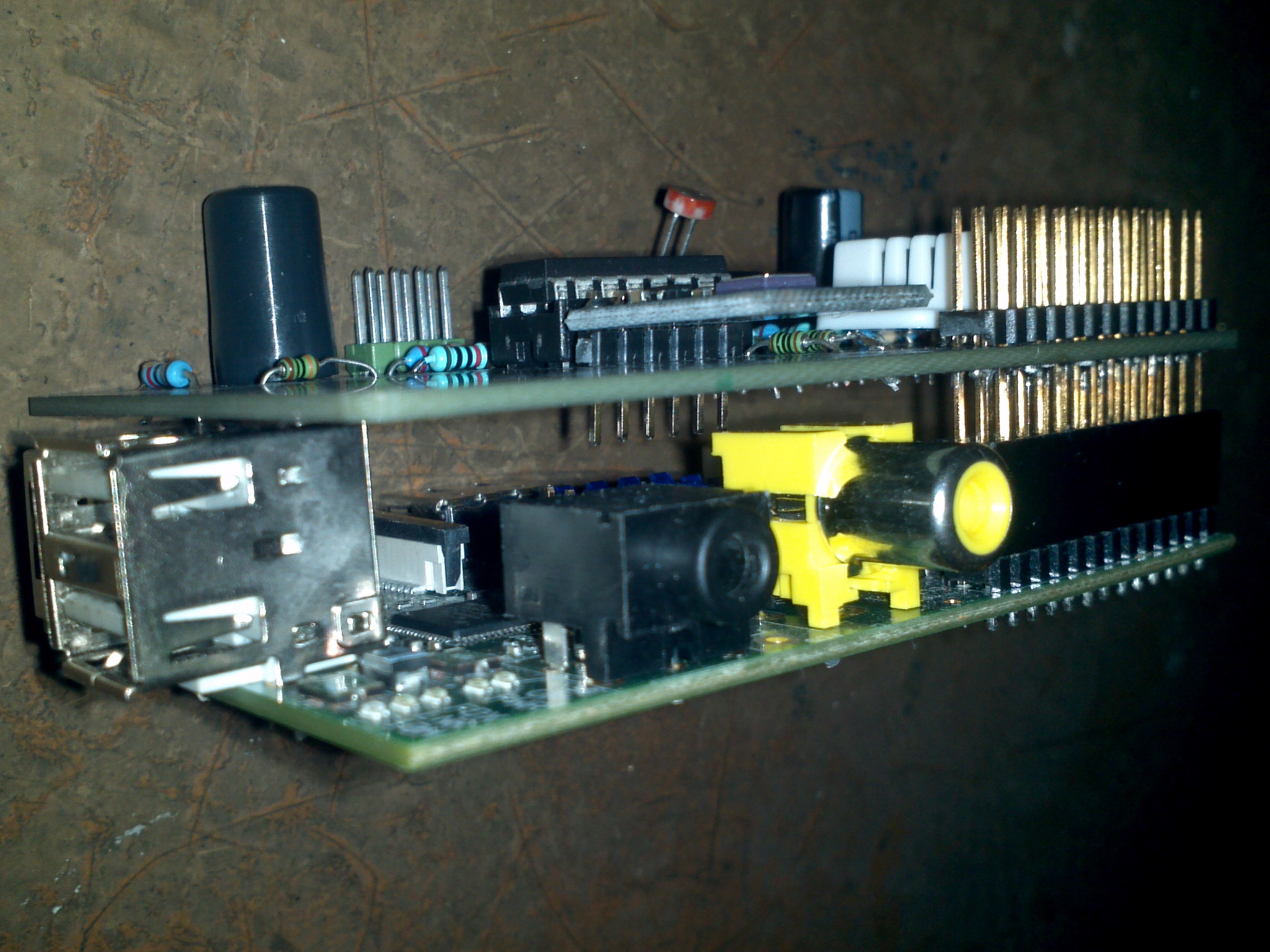
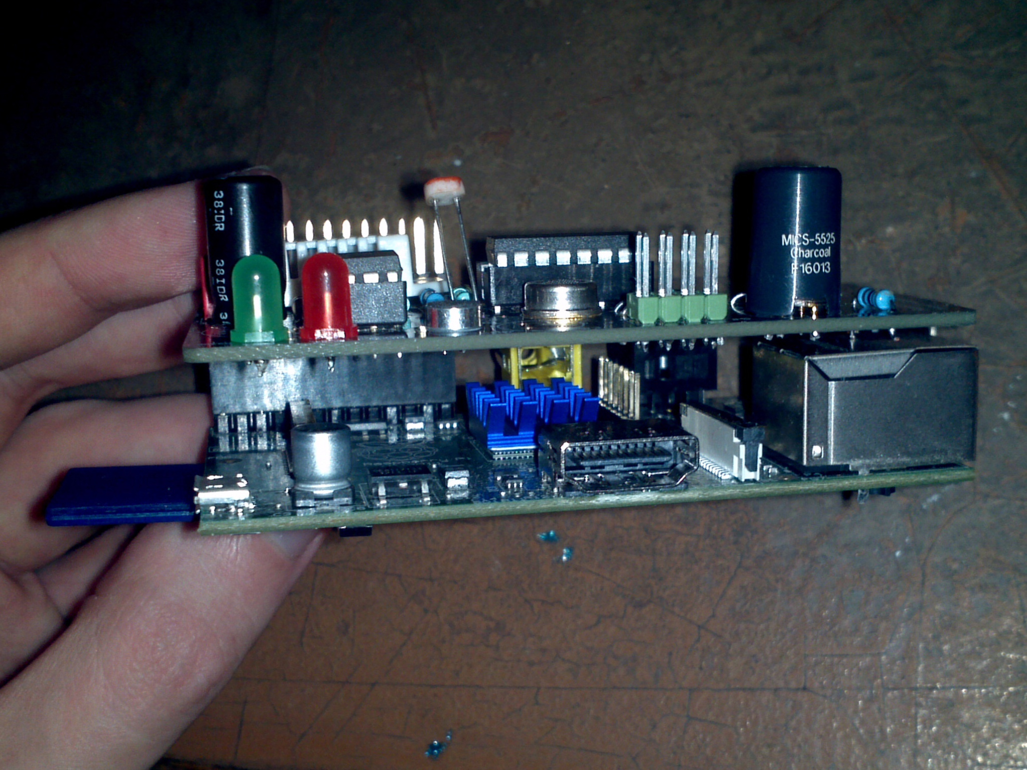
 Done!
Done!
 And the reverse
Soldering on the Pi connector was interesting. 26 very tightly spaced little contacts that I soldered from the bottom. That side with a huge chunk of plastic in the way. Somehow it seemed like a better idea than approaching it from the top, but I don't know really. I used a GPIO ribbon cable to work out how much the connector on the bottom needed to stick through.
 Sticking it on a pi
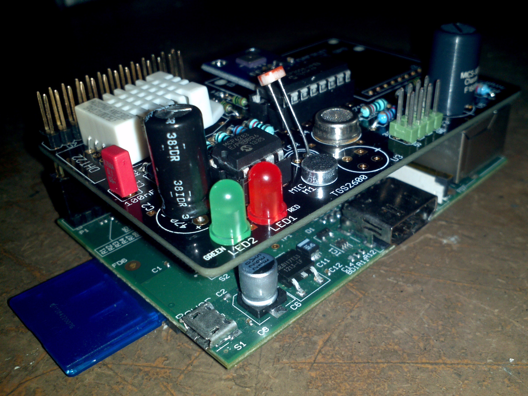
 A pretty compact package
After putting the AirPi on top of a Pi, I realised that the placing GPIO header placing turned out to be near perfect. But due to dumb luck. If I hadn't had the GPIO ribbon idea, I would have would up having to re-solder it. You can see how darn near it is to there not being enough clearance. Ouch.
 Eeek! That's close!
And then to test if it works. It's important to note that the different board has a different software version to go with it, this time off of the trunk of the Git repository. Configuring is easier this time around though as the software matches the hardware perfectly. Only two minor configuration changes are necessary. One in sensors.cfg to set the correct I2C bus. The other in outputs.cfg to disable Xively as I'm only testing.
 I put it in my half disassembled LEGO case for powering up to test
It runs perfectly out of the box! You can see the green LED lighting up on a reading. Output is shown below. I'm not entirely convinced the temperature is correct, but everything else is reasonable, I think... At this point I struggle from the same problem as I did last time, which is I still haven't quite worked out how to interpret the data. I admit though that this version of the software is more honest. Calling it Ohms for an analogue sensor reading without calibration is probably the correct way to go.
Time: 2014-02-11 20:37:56.611572
Temperature: 32.4 C
Pressure: 977.71 hPa
Relative_Humidity: 25.7000007629 %
Light_Level: 7698.96193772 Ohms
Nitrogen_Dioxide: 7607.57314974 Ohms
Carbon_Monoxide: 301176.470588 Ohms
Volume: 90.3225806452 mV
Uploaded successfully
I'm not entirely convinced about the utility of the microphone. Maybe an indirect measure of wind? All told though a pleasant and funkit to build. The difficulty is about average. Some bits to solder are tricky, but nothing's impossible, especially if you have some previous experience. This kit has now been sent off to Lubo, our electronics specialist, for additional compatibility testing with the MoPi. In the meantime I continue to collect data from my breadboard prototype to see what I can do with it. Stay tuned for a report!
 The end