MoPi 2: Hot-Swap Mobile Power for the Pi
MoPi 2 is mobile, hot-swap and 24/7 power for the Raspberry Pi.
I want one! (how to order)
(In early 2014 we ran a Kickstarter campaign to fund the first production version, which was delivered in June 2014. In 2018 we've released MoPi-2, the best mobile power solution for the Pi! You can get MoPi-2 from Pimoroni.)
MoPi-2 works with all Pi models, including the latest Raspberry Pi 3 B+. The product is made in the EU.
(Looking for the old MoPi? It's here!)
1.Pi To Go !
MoPi-2 is mobile and 24/7 power for the Pi 2 and Pi 3 boards. On your bike, up a tree, or for your home server: we've got you covered. MoPi-2 is successor of the well-known MoPi.
![]()
MoPi-2
features:
Two power inputs via standard screw terminals — for standard batteries, car power sockets, old laptop, supplies, solar panels, wall adapters and more
Hot-swap power replacement without stopping work
Shutdown the Pi cleanly when batteries discharge
Right-angled power switch accessible even another PCB is stacked on top
Usable as a UPS (uninterruptible power supply) by attaching both batteries and mains
Wide input voltage range: 6.5V to 24V 1
Ability to deliver up to 2.5A @ +5V to the Pi and attached additional PCBs or devices
Low power consumption: 15mA when is working, 0.5mA when is sleeping and only 15 µA when is off ! (more than 10 times less than the average battery self discharge rate)
Auto-off when input voltage reaches 6.0V, protecting the batteries from over-discharging.
Additional 2-pin terminal for an external battery charger (this is just a gate, all charging functionality depends on the charger itself)
On-board LED indicators and on screen Linux system notifications
Configuration of multiple battery chemistries and number of cells from a UI on the Pi
Full API in Python, plus a shell-friendly command-line interface
Very low-profile (3.5 mm), bottom entry, 40-pin GPIO connector allowing stacking of other boards on top of the MoPi-2
PCB pads for external power switch and +5V
Control of external 5V relay
Two-way communication via the I2C bus
Remote power-off: tell MoPi-2 to power down the Pi when logged-in remotely (after a clean shutdown, of course)
Timer-based wake-up: tell MoPi-2 what time you want your Pi to wakeup, then power it down and MoPi-2 will boot the Pi as requested
Supports Raspberry Pi 2, Raspberry Pi 3 and Raspberry Pi 3 B+ models.
2.User Guide
2.1.Warnings!!!
DO NOT plug MoPi-2 onto your Pi while the Pi is powered up!
DO NOT touch electronic components when they're powered up — you may damage them, or burn your fingers!
AVOID handling circuit boards when charged with static!
ALWAYS read the small print on all components supplied with your MoPi-2
ALWAYS treat batteries and other power supplies with respect — if abused the energy they contain may surprise you in dangerous ways!
DO NOT feed MoPi-2 to your dog, eat nuts if you're allergic to them, or lose your sense of humor.
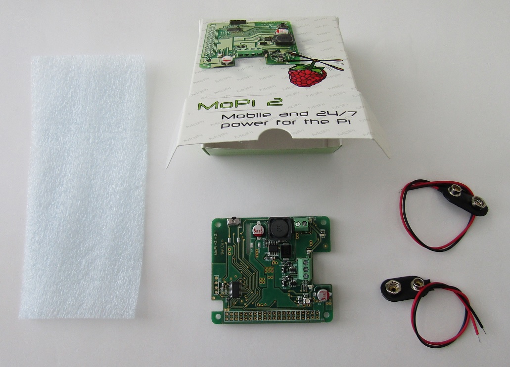
2.2.Delivery Kit
The MoPi-2 is delivered in small cartoon box. Its contents is shown below. On the sides of the box is printed a link to the website containing this manual. On the underside of the box there is a QR code pointing to the same site.
2.3.MoPi-2 LEDs and Connectors
The MoPi-2 top side is shown on the picture below. Description follows.
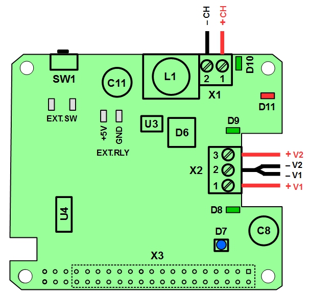
X1 – screw terminal for external charger. Pin #1 is live wire (typically red), pin #2 is ground wire (typically black).
X2 – screw terminal for power sources. Pin #1 is for live wire of power source #1 (typically red), pin #3 is for live wire of power source #2 (typically red), and pin #2 is for ground wires of both sources (typically black).
X3 – GPIO connector. The PCB has holes for all 40 pins, while the connector itself, located on the bottom side of the PCB, takes the first 34 pins only. The pin #1 is marked with small square.
D7 – RGB status LED. Indicates the actual voltage level of the power source. Blue light means battery full, green light means battery good, red light means battery low (discharged), flashing red light shows that shutdown is in progress.
D8, D9 – two green LEDs showing the power sources status, D8 for source #1, D9 for source #2. Steady light means battery full, flashing light means battery discharged, light off means battery not connected.
D10 – green LED showing the charger gate status. Steady light means the gate is open, otherwise the gate is closed. The battery connected as source #2 can be charged only when the gate is open.
D11 – flashing red LED showing high power consumption (close to 2.5A or higher). It is off at lower consumption.
SW1 – power switch. Pressed for 2 seconds turns MoPi on, pressed for 3 seconds starts MoPi shutdown. Pressed for 10 seconds turns MoPi immediately off.
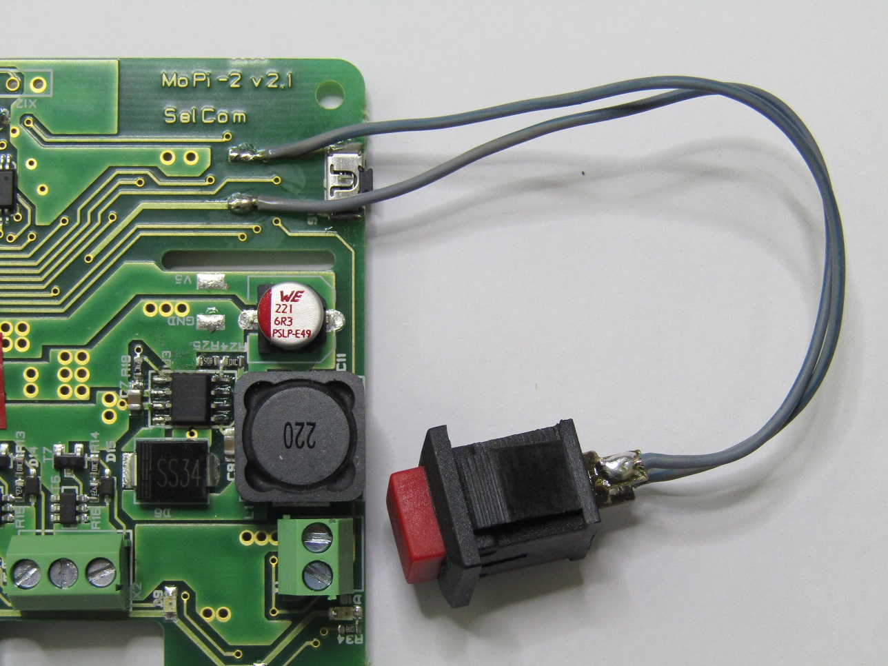
EXT.SW – soldering pads for external power switch.
EXT.RLY – soldering pads for external 5V relay. +5V is for live wire, GND is for ground wire.
2.4.Installation and Use
2.4.1.Quick Start
If you are in hurry:
1. Install the battery monitoring software and shutdown:
sudo apt-get update
sudo apt-get install simbamond2
sudo poweroff
2. Connect your batteries and charger to the MoPi-2
3. Attach the MoPi-2 to your Raspberry Pi and press the Power Switch for 2 seconds
For more details on each step, see below.
2.4.2.Installing the Software
As noted above, you can install the battery monitoring software like this:
sudo apt-get update
sudo apt-get install simbamond2
(We assume you're using the Raspbian flavour of Debian GNU Linux here.)
Occasionally this method may cause glitches (if you've a very old version of the rest of the operating system installed, for example). The most cautious recipe is to update your firmware and the operating system, then install the MoPi-2 software, and to reboot between each step:
sudo apt-get update
sudo apt-get upgrade
sudo reboot
sudo rpi-update
sudo reboot
sudo apt-get install simbamond2
sudo poweroff
Note that if you're installing the software without MoPi-2 attached, or without power attached to MoPi-2, you will get a warning message5; just ignore it at this point!
2.4.3.Connecting the Power and the Charger
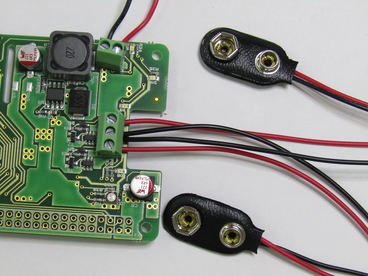
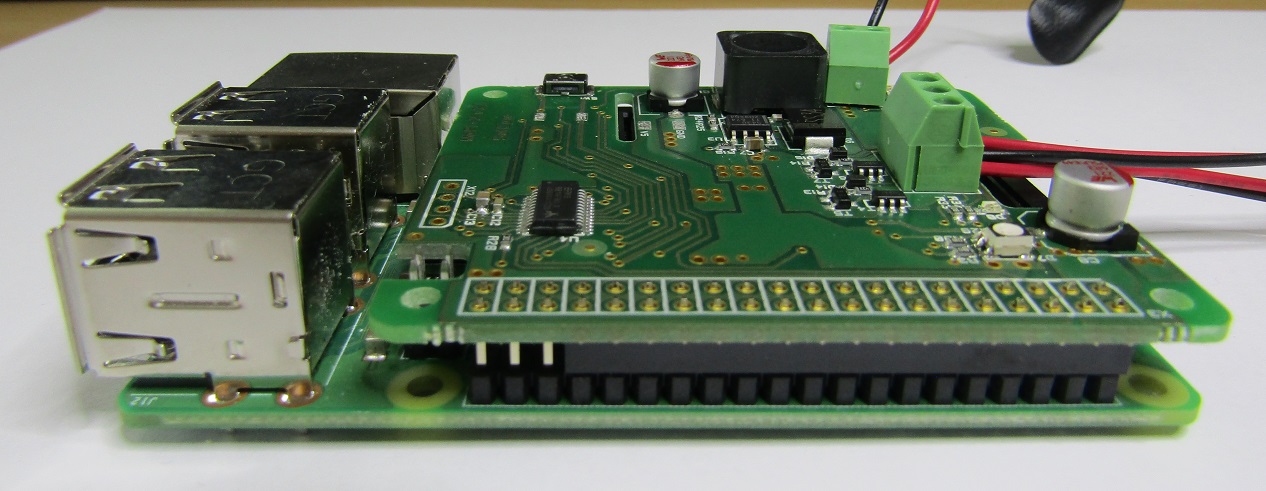
Next connect one or more power supply to MoPi-2 using the screw terminals X2 on the topside of the board. When connecting the power sources (e.g. two battery packs, or one solar panel and one battery pack) follow the above description and the picture below. The same concerns the external charger, if use.
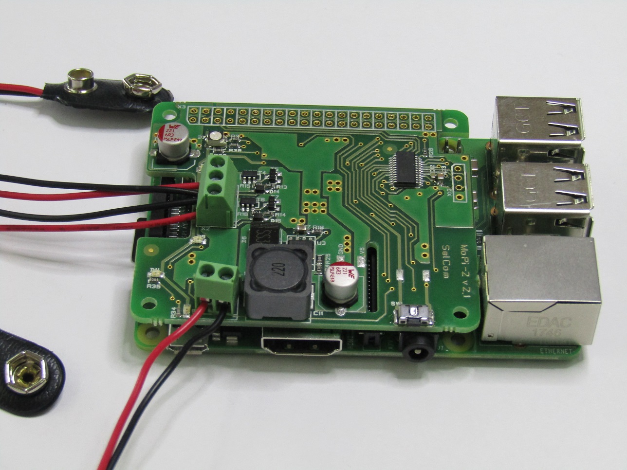
2.4.4.Connecting to the Raspberry Pi
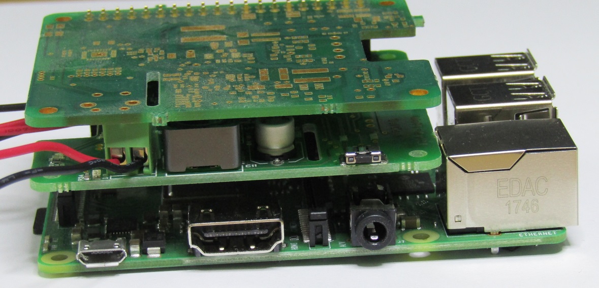
Gently push fit MoPi-2 onto your Raspberry Pi's GPIO pins. Make sure you do this with the Raspberry Pi turned off, or you risk a reset. Please note that MoPi-2 connector has 34 pins, not 40, and it must be left aligned with the Pi connector, matching both pins #1.
|
|
|
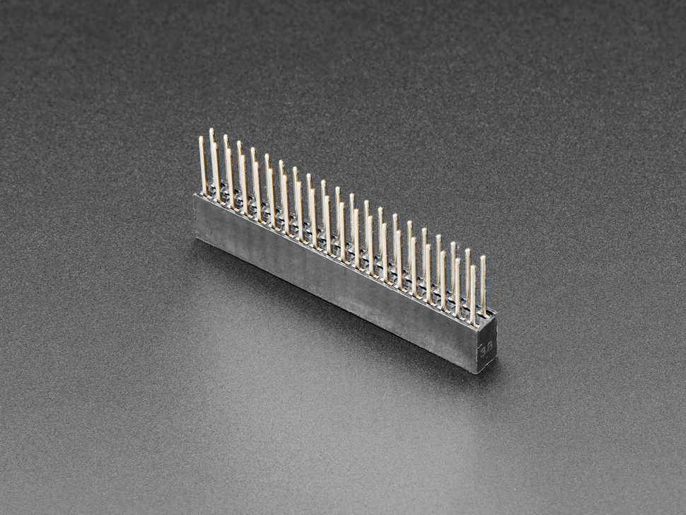
If you want to use MoPi-2 in combination with another Pi add-on board you need
to buy one 2x20-pins extra-long GPIO connector (e.g. by Adafruit) and push this connector fit onto your Raspberry Pi GPIO pins
|
|
|
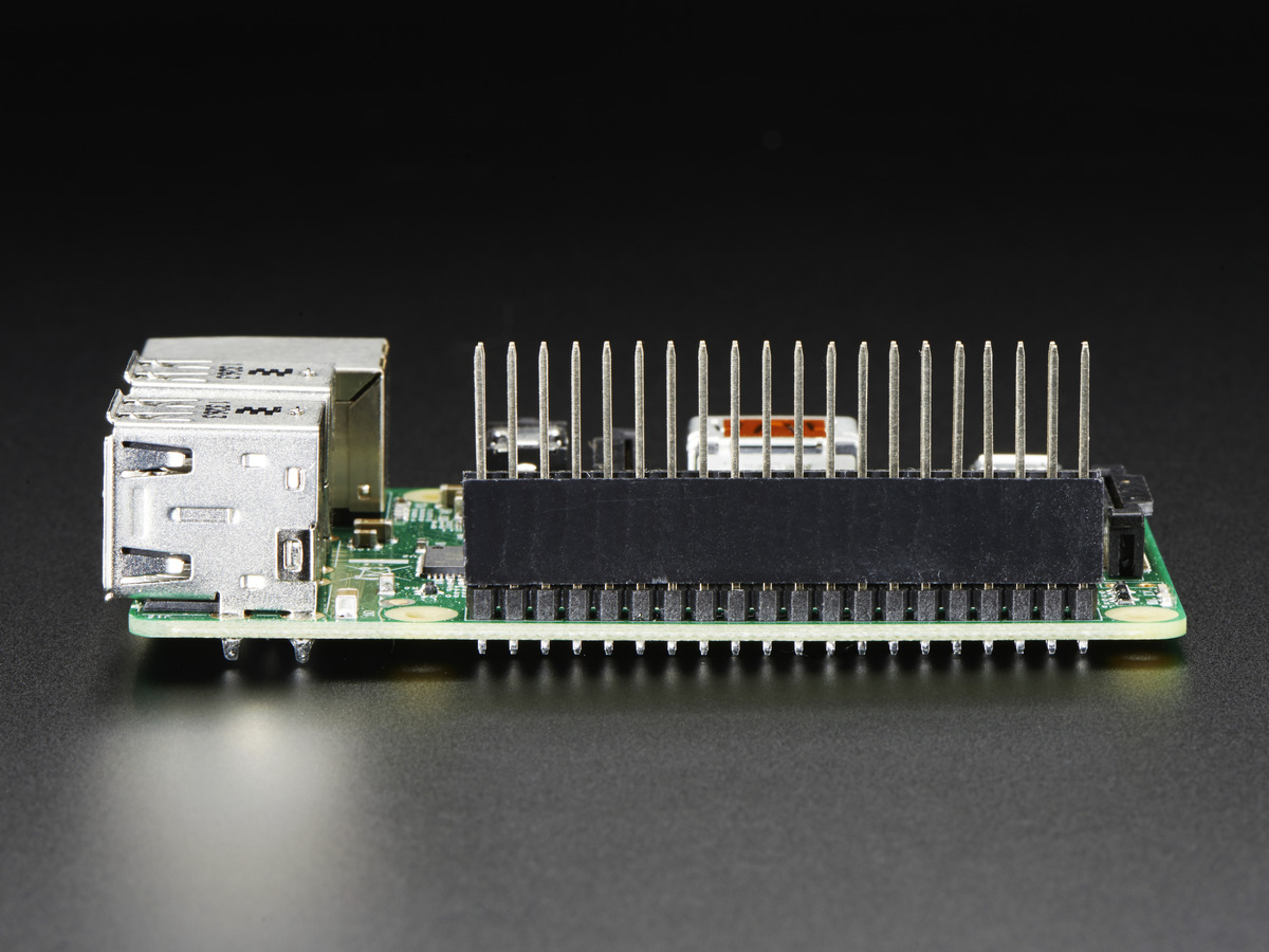
push fit MoPi-2 onto the connector, and
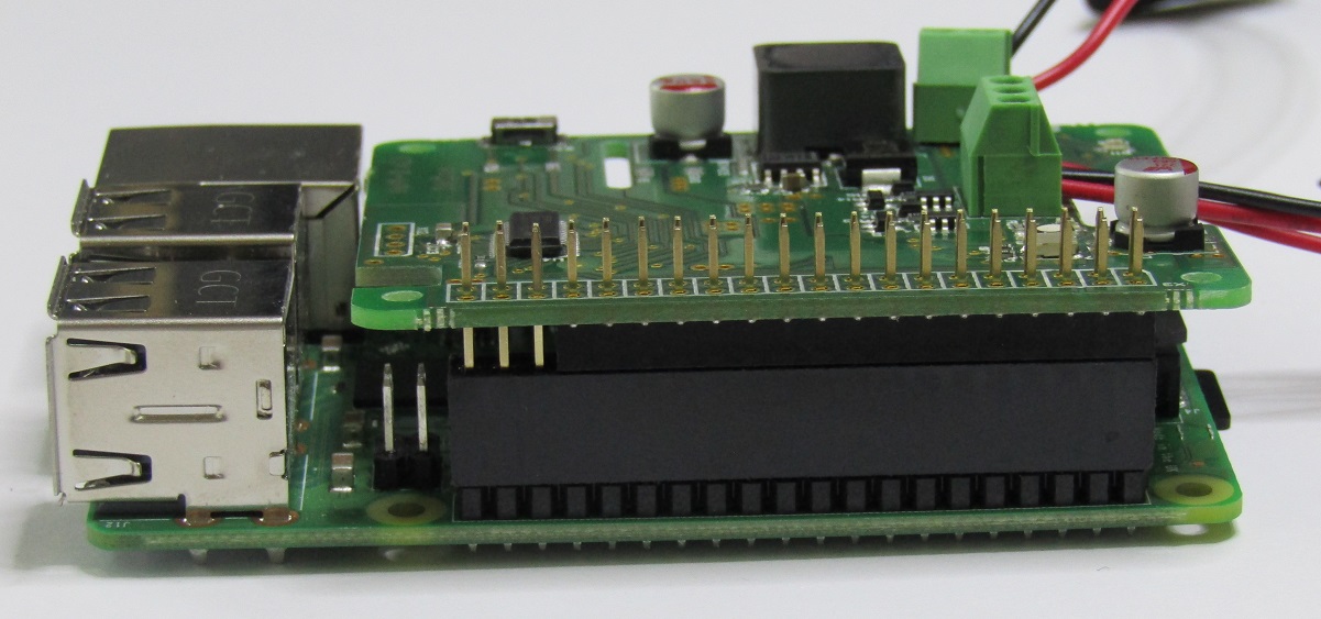
push the other board to fit on top.
|
|
|
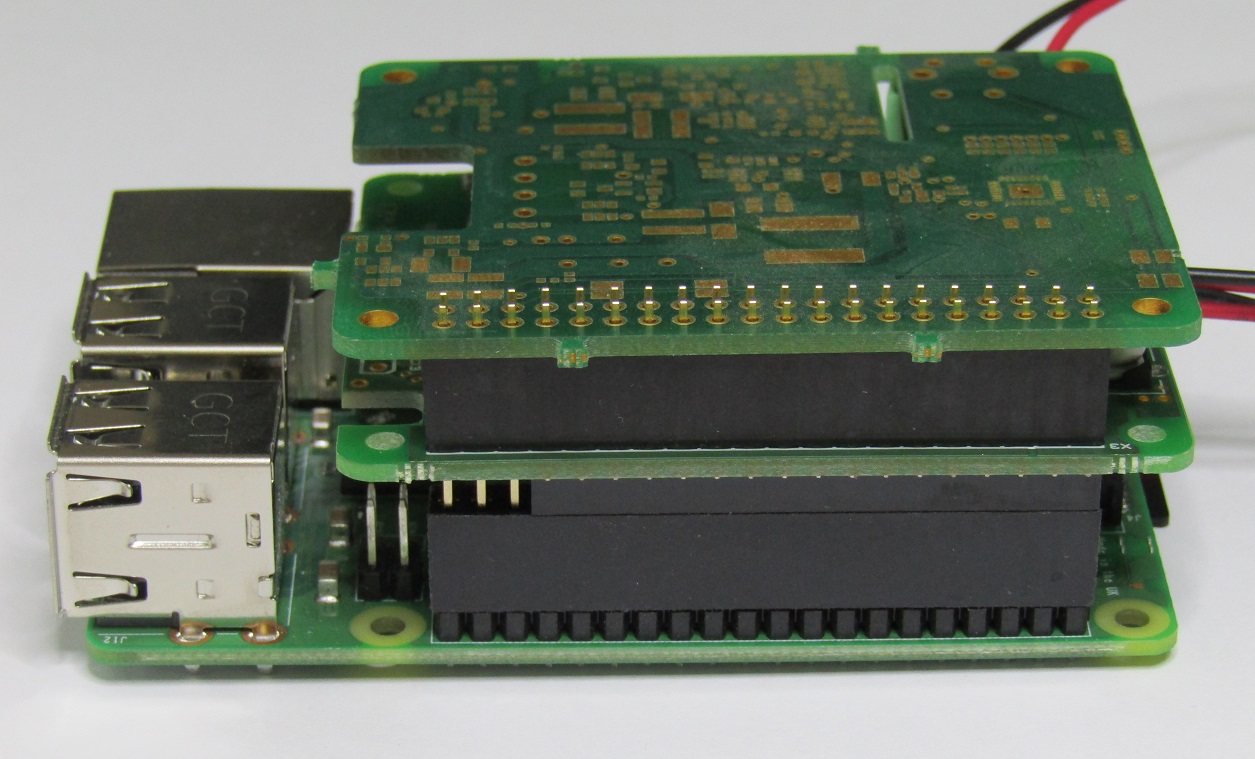
(An empty MoPi-2 board has been used as example for second add-on board).
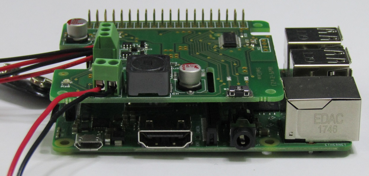
If the other add-on board has an extra-long connector, then it can be connected to the Pi and MoPi-2 stacked on top of it.
Note: MoPi-2 should be compatible with all Pi add-on boards, as it only use the I2C bus, which supports the connection of multiple devices.
2.4.5.Turn On, Turn Off
When MoPi-2 and the Pi are powered off, press the power switch for 2 seconds to turn them on.3
When the Pi is powered on, press the power switch for 3 seconds to turn it off. This will shut the Pi down cleanly (which can take up to around 30 seconds). If you hold the power switch down for 10 seconds, the power will shut down immediately.
2.4.6.Connecting External Power Switch and/or Relay (Optional)
In case of need of external (remote) power switch, it has to be soldered to the two pads labeled EXT.SW. See the next picture.
In case of huge power load, bigger than the MoPi-2 is able to take, an external 5V, e.g. 10A relay is needed. It has to be soldered to the pads labeled EXT.RLY. Follow the pads polarity and the picture below. The electrical diagram of the relay circuit is also given below.
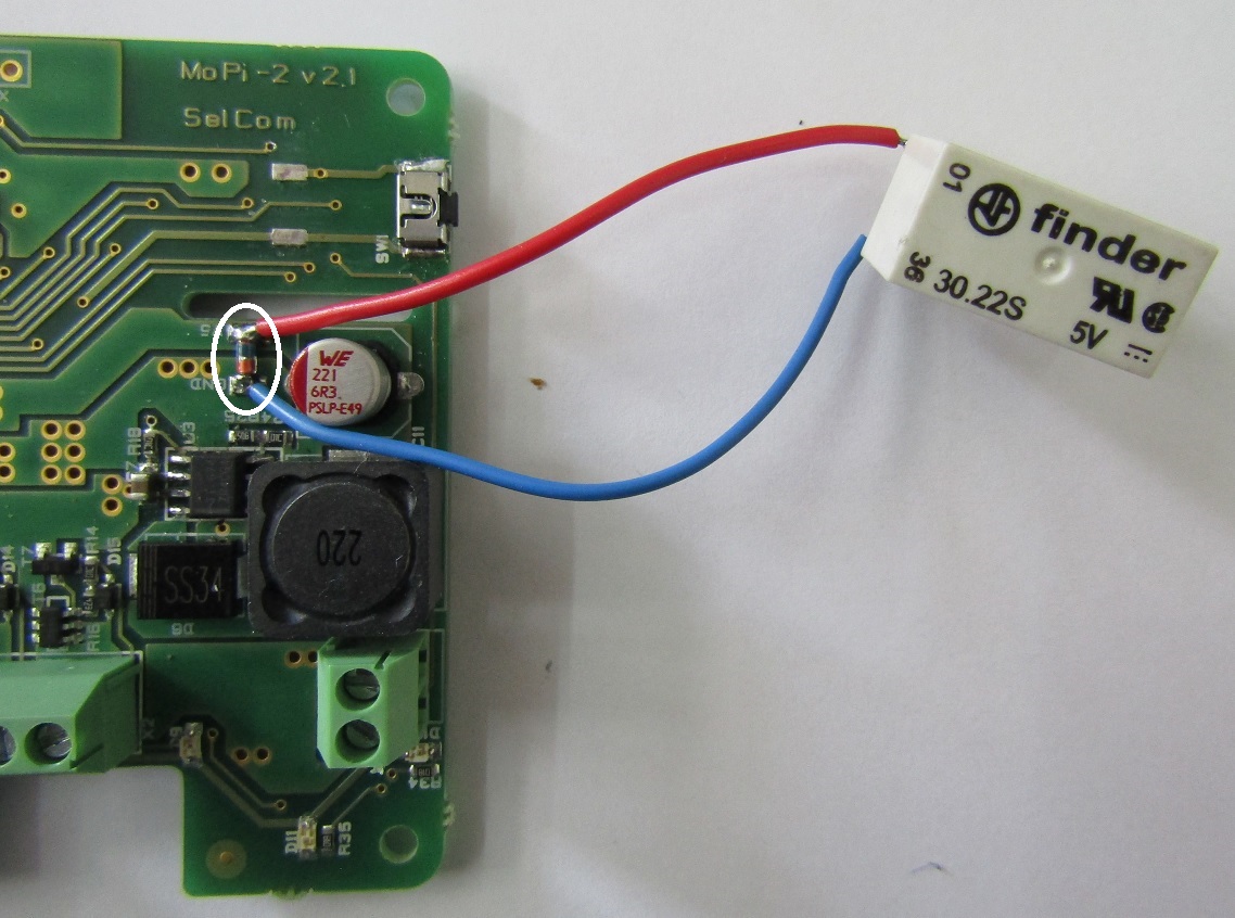
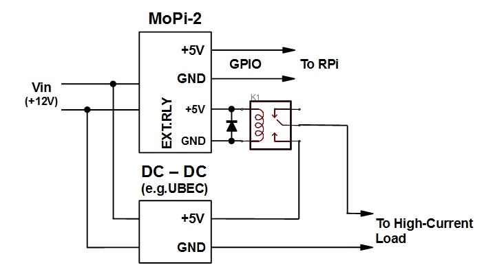
A
5V 10A relay and a rectifier are soldered to the EXT.RLY
pads. Note both polarity. If MMELF case is used, the rectifier fits
exactly on the pads (see the white oval on the above picture). Then
MoPi-2 is fit on the Pi via the GPIO connector. An additional
DC-to-DC converter, e.g. 3A UBEC, as added to power the external load
trough the relay contacts. Thus the load will be powered on and off
in parallel with the Pi, under MoPi control.
2.5.Choosing and Configuring Batteries (Etc.)
The short story is this:
Any power supply connected to the MoPi-2 must be capable of at least 6.5V under load, and no more than 24V.1
The MoPi-2 must be configured correctly both to avoid damage to rechargeable batteries and to avoid unexpected shutdowns!
How do I configure MoPi-2? There are 3 ways:
1. Use the on-board default — easy peasy!
2. Use the Configuration Tool4 on your Pi — straightforward.
3. Use the command-line interface, and/or edit the daemon config data on your Pi — advanced.
Let's take each of these in turn...
2.5.1.Choosing Default Supply Profile
The default supply profile is eight NiMH AA rechargeable batteries.
2.5.2.Using the Configuration Tool on the Pi
If you're using a supply that doesn't match MoPi-2's default profile, you need to run a configuration utility on the Pi itself. This will prompt you to enter details of the supply, then calculate appropriate values to send to the board over I2C. It will also store the config data and resend it to the board after reboots as necessary.
To start the configuration tool open a terminal and do:
sudo mopi
The tool operates in the same way as the Raspberry Pi's configuration tool (raspi-config). Select the option to configure one or both of MoPi-2's supplies, and then:
Type of supply. This is one of rechargeable battery, non-rechargeables (like standard Alkaline batteries), or non-battery (like an AC adapter).
Number of cells. This is the number of individual battery cells in your supply. Note that some batteries incorporate several cells — e.g. a9V PP3 has 6 cells internally.
Battery chemistry. The type of battery you're connecting. For example "Alkaline" or "NiMH" or “Li-Ion” or "N/A" for non-battery supplies.
After entering this data the tool will give details of the values it has calculated and offer to write these to the MoPi-2 board. There is detail of these values and how the tool works below.
2.5.3.Command Line, Python API and Daemon Config Hacking
Finally, if you want more control, or the other methods are insufficiently scary, you can use the command-line tool directly, or edit the simbamon daemon configuration data, or write code using the Python API.
A quick demo of using the cli setting the default 8 NiMH profile:
sudo mopicli -wc 1 11200 9800 9350 8500
For more details, see the software below.
2.5.4.Minimum Number of Cells
The minimum number of battery cells that have to be used to power the MoPi-2 depends on the battery chemistry. Different battery cells have different voltage level, hence different minimum number of cells. Below are given the minimal number of cells for each battery chemistry.
|
Battery Type |
Single Cell Voltage |
Number of Cells |
Total Voltage |
|
NiMH |
1.2 V |
6 |
7.2 V |
|
Li-Ion |
3.6 V |
2 |
7.2 V |
|
LiPo |
3.7 V |
2 |
7.4 V |
|
LiFePO4 |
3.3 V |
3 |
9.9 V |
|
Alkaline |
1.4 V |
5 |
7.0 V |
|
Lead Acid |
2.0 V |
4 |
8.0 V |
2.6.Troubleshooting and FAQ
2.6.1.Wh...?
>>> Which GPIO pins does MoPi-2 use?
Pins 2 and 4: 5V out
pins 3 and 5: I2C bus
pin 6 and any other grounded pin: 0V.
>>> I get a warning during software installation
If you're installing the software without MoPi-2 attached to the Pi, or MoPi-2 off, you will get this warning message:
/usr/sbin/simbamon: /usr/sbin/mopicli not working; MoPi-2 not attached or powered? (mopicli. I2C bus input/output error on read word. Check bus? Check connection?)
In this case you can safely ignore it.
>>> How do I connect another board?
If you want to use MoPi-2 in combination with another Pi add-on board you need a) to buy one 40-pin extra-toll GPIO connector (e.g. Adafruit …...), b) gently push this connector fit onto your Raspberry Pi's GPIO pins, c) gently push fit MoPi-2 onto the connector, and d) push the other board to fit on top. See the picture.
If the other add-on board has an extra-toll connector, then it can be connected to the Pi and MoPi-2 stack on top of it.
MoPi-2 should be compatible with all other Pi add-on boards, as we only use the I2C bus, which supports the connection of multiple devices.
>>> I connected a power source, press the switch but MoPi-2 won't start...?
MoPi-2 needs a minimum of 6.5 volts to run. Then it also has a (configurable) "safe depth of discharge" setting to prevent damage to rechargeable batteries. If the sources connected aren't higher than the highest of these, MoPi-2 will refuse to power the Pi. If there is enough voltage to run the microcontroller, it will blink the relevant green LED a few times to signal the problem.
Solutions:
Configure the MoPi-2 to accept the supply (if it will reliably exceed 6.5 volts under load).
If it still doesn't start, the batteries may be discharged! Connect some freshly charged ones or a higher voltage supply.
>>> What type of regulator chip is it? What is the voltage range?
MoPi-2 uses TPS5430DDA 3A step-down voltage converter. The input voltage range is specified as 6.5V to 24V. There's no step-up circuitry so the battery or solar panel rig or etc. has to supply 6.5V at minimum. Consider connecting multiple batteries or panels in series to increase voltage.
>>> Can I access the voltage data on MoPi-2 from the Pi?
Yes!
The software on the Pi that talks to MoPi-2, simbamond, is open source and available here: https://github.com/hamishcunningham/pi-tronics/tree/master/simbamon (See also http://pi.gate.ac.uk/pages/download.html.) The Raspbian maintainers have added simbamond to their repository, so you can install it in the same way as any other Pi software.
Simbamond listens to MoPi-2 and logs the data in a standard manner, which other applications can then consume as required. There's also a Python API and a command-line interface (CLI):
sudo mopicli -v -v1 -v2
For more details, see the software below.
>>> Can I combine mains and solar power?
Yes!
This should work so long as you connect the mains-derived power to one of MoPi-2's inputs (it will have to be a supply >= 6.5 volts). MoPi-2 will then use mains whenever the solar output dips below the mains supply. The ideal would be a solar panel rig that outputs e.g. 15V coupled with a 12V mains supply, or some similar config.
Note also that the Pi will draw significant current, depending on the model and the peripherals, and you will needs sufficient panels (and sunshine!) to generate the requisite power. As a very rough guide, we've had some success with three 10W panels running a model B (without peripherals).
>>> How do we avoid deep discharge of rechargeables?
The short answer it to shutdown before it happens. Rechargeable batteries don't like being completely discharged. We always need to stop drawing from the battery at some distance above some minimum voltage level. This level varies for different battery chemistries (NiMH, LiPo, lead/acid, etc.) and for different numbers of cells (eight AAs vs. two PP3s vs. one car battery, etc.).
MoPi-2 listens continuously to the voltage level on the battery inputs. How does it know when that level is getting low? Let's identify two separate low-level points: first, the absolute low voltage level is the point where our micro-controller can no longer reliably run the switching regulator to produce a constant 5V (around 6.5 volts). The second low voltage (critical) point is just above the deep discharge level, which depends on the batteries attached. When you use the configuration tool this critical voltage point sent to the MoPi-2. As long as you've correctly configured your batteries, we should be avoiding deep discharge.
When the MoPi-2 decides the input voltage is critical (for either or both of its two supplies), simbamond warns the user and shuts down the Pi cleanly (from software first, using "sudo halt", and then by cutting power). How do we decide when to do this, that is to say, how do we pick the critical voltage level? We've done some research on batteries. For eight NiMH 1.2 volt cells the critical voltage is around 8.5 volts. For non-rechargeables, or solar panels or a water turbine, it is the same as the absolute low level (6.5V) as these can't suffer deep discharge.
The critical voltage level is kind of short notice though for replacing batteries. The configuration tool also specifies a low voltage level, which is when the LED on the MoPi-2 turns red and you start receiving low battery notifications. This is set to be 1.1*critical, so for 8 AA NiMH batteries it's 9.3 volts. (There are other voltage levels defined too. Read more later.)
>>> Mkmod or libkmod errors when installing or upgrading.
The installation of simbamond requires enabling I2C. If it is not enabled by default, there are two ways to do this, depending on what version of Raspbian we're running. At present the installation script tries to do both, with the intention of catering for the maximum number of variants. This does mean that you may see errors like the following. If everything works after a reboot, ignore them; otherwise:
try installing i2c-tools and i2cdetect to see if the bus is enabled
i2cdetect -l will return nothing if I2C is not enabled, or something like "i2c-1 unknown ..." if it is enabled
If you get a message like
"libkmod: ERROR ../libkmod/libkmod.c:554 kmodsearchmoddep: could not open moddep file '/lib/modules/3.6.11+/modules.dep.bin'"
when installing, try a reboot followed by
sudo apt-get -f install
>>> The I2C bus doesn't work after install.
If the I2C bus appears not to be working after installing simbamon, try a reboot. Sometimes the Python SMBus module appears not to load correctly.
>>> How do I add a remote power switch?
There's a description here.
>>> How do I add an external 5V relay?
There's a description here.
>>> What do the status bits mean?
MoPi-2 returns status data to the Pi over i2C — if you need to interpret these:
mopicli -sv will give you the decoded status
check the source code to see the meaning of each bit.
>>> How can I read the MoPi serial number?
Type sudo mopicli -sn and you will get the device serial number:
Serial number: XXXX
>>> How do I ...?
Another good place to look is the GitHub issues list (click on the "closed" list to see them all).
If you're still stuck, raise a new issue?
Good luck!
2.6.2.Pi Models: 2, 3, 3 B+
MoPi-2 is tested and is working fine with the Raspberry Pi 2 Model B, Pi 3 Model B and Pi 3 Model B+. See above.
3.The MoPi-2 Hardware
The MoPi-2 simplified schematic diagram is shown below.

3.1.Powering the Pi
MoPi-2 has two power inputs, labeled BATTERY #1 and BATTERY #2 (connector X2, pin #1 and pin #3 respectively; pin #2 is GND). They are connected to MOSFET switches T4 and T6 respectively. The T5 and T7 comparators open this switch whose input voltage is higher. The corresponding green LED, D8 or D9, located next to the power inputs, lights up. The other input voltage, if such exists, is backing up the MoPi-2 work and takes over immediately after the first input voltage becomes lower than the second one.
The +5 volts to the Pi is generated by a highly efficient, wide-input, 3A switch mode voltage converter U3. It starts when the power switch SW1 is pressed and hold for 2 seconds. Between U3 output and GPIO connector pins a “smart diode” T10 is placed to protect Pi and MoPi-2 from opposite switching of their power supplies.
The MoPi-2 functionality is implemented by a firmware flashed in microcontroller. It does voltage level monitoring, level signaling (via the LEDs and the I2C interface), and on/off switching of the +5V supply to the Pi. Battery voltage levels are measured using the built-in microcontroller analog to digital converter and compared to predefined discharging profile (default or programmed via I2C commands). Each profile define four voltage levels: battery full, battery good, battery low, battery critical) A RGB LED D7 lights on blue, green or red to indicate the actual voltage level. Its state is also accessible via I2C status command. During operation, the microcontroller continuously monitors the voltage level, and when it falls beneath a low battery level that it believes leaves only a few minutes of operational time, it switches the RGB LED to red. Simultaneously the green LED of the low battery starts flashing, indicating that the pack needs replacement. If the user connects to MoPi-2 another, fresh battery pack, the work continues. Another possibility is the user to force clean shutdown pressing and holding the power switch SW1 for 3 seconds. If nothing changes and the battery continues to discharge down to a critical level, then the RGB LED starts flashing red and MoPi-2 forces clean shutdown.
Notes:
The MoPi-2 default discharging profile is for 8 NiMH rechargeable batteries with the following voltage levels:
Battery Full 11.2V
Battery Good 9.8V
Battery Low 9.35V
Battery Crytical 8.5V
User alerts and clean shutdown are combined functions of MoPi-2 and installed in a Pi Simbamon daemon.
3.2.Load Signal
MoPi-2 continuously monitors the magnitude of the load current (current to the Pi). If it becomes near 2.5A, the red LED D11 starts flashing. The LED goes off when the magnitude drops down to 2.0A or less.
3.3.Charger Gate
One of the MoPi improvements is the ability to charge the batteries without disconnect them. To implement this feature MoPi-2 has additional gate, connector X1, where an external charger can be connect. The battery pack has to be connected to BATTERY #2 input. The other input, BATTERY #1, can be use for another power source, e.g. wall adapter. MoPi-2 will use the BATTERY #1 input while its voltage magnitude is higher than the BATTERY #2 magnitude. The charger gate will open if
1) there is a charger connect to it,
2) there is a battery connected to BATTERY #2 input, and
3) BATTERY #1 voltage is higher than BATTERY #2 voltage.
All charging parameters, such as magnitude of the current, duration of the charge, termination etc depends entirely on the functionality of the external charger. Mopi-2 will terminate charging and close the charger gate only if
1) the charger or the battery are disconnected,
2) the BATTERY #1 voltage becomes equal to or less than BATTERY #2 voltage, or
3) MoPi-2 shuts down.
When the charger gate is open, the green LED D10 lights on.
3.4.Microcontroller
The microcontroller (with embedded firmware) implements all the functions related to voltage level monitoring, level signaling (via the LEDs and the I2C interface), on/off switching of the +5V supply to the Pi, and charger gate on/off. An 8-bit low-power EFM8BB1 by Silicon Labs is used.
3.5.MoPi-2 Modes
MoPi-2 has the following modes of operation:
Normal Mode – MoPi-2 is started and supplies +5V to the Pi. The power consumption is 15mA.
Sleep Mode – MoPi-2 enters this mode when an Power Up Delay I2C command has been issued before Shutdown command. The +5V to the Pi are switched off, the LEDs also. Only the microcontroller is counting the preset delay. When end of the count is reached, MoPi-2 wakes up switching to Normal Mode. The power consumption in Sleep Mode is 0.5mA.
Off Mode – MoPi-2 initial state or result of an Shutdown command. Most of the components, including the microcontroller are disconnected and MoPi-2 takes 15µA only! To switch on and go to Normal Mode the power switch has to be pressed for 2 seconds.
Idle Mode – If MoPi-2 is running without load (probably the Pi is powered up via its micro-USB connector or the PCB is not inserted on the GPIO pins), the firmware switches the device in Idle Mode. The voltage regulator is on generating +5V, but they are split from the Pi by the “smart diode” T10. The status LED flashes slow in blue or green in dependence of the input voltage level. Once a load is applied, e.g. the Pi's 5V goes off and T10 opens up to power the Pi, MoPi-2 switches to Normal Mode keeping the Pi to run smooth. The status LED lights steady after the switching.
4.The MoPi-2 Software Suite
This section describes how the MoPi-2 software suite works and how the architecture of MoPi-2 hangs together.
There are four main parts of the puzzle:
A daemon which runs in the background on the Pi, which is called simbamond (simbamon daemon, or SImple BAttery MONnitor daemon). It is available as a package for Raspbian, and installing it pulls in all MoPi-2 software.
An interface that communicates with the MoPi-2 hardware over the I2C protocol. This interface is wrapped up as a Python API.
A command-line tool that uses the Python API and provides a language-neutral portable method for talking to the board from the Pi.
A configuration user interface that simplifies the process of setting up MoPi-2 to deal with different types and numbers of batteries, and other types of power supply.
All of the code for these components is available on GitHub.
The rest of this section discusses each of the main elements in turn, describes how to check up on the beast as it runs, and finishes up with more detail of the implementation of the daemon.
4.1.simbamond, the simbamon daemon
When the Pi (or any other Linux system) boots, several system services are started that will run continuously until the machine is shut down again. These services are called daemons, of which simbamon is one. The first point of entry, used by the operating system to start, stop, etc., is an init (think initialisation) script: /etc/init.d/simbamond. This script (which you can think of as a wrapper for management) calls another script to do the real work: /usr/sbin/simbamon.
One of key features of MoPi-2 is that it supports many different types of batteries and many other types of power supply (from solar panels to elastic bands!). Coping with the requirements of all these monsters needs a huge wodge of configuration data, which (following Debian Linux convention) lives in /etc/default/ in a file (again, confusingly) called simbamond.5
Together these three script files make up a new system service that polls the MoPi-2 hardware every couple of seconds and shouts loudly when an electron shortage appears on the horizon. If no one is listening and the shortage gets acute, the daemon tells the Pi to take a rest and issues the shutdown command.
There is more detail below.
4.2.The Python API
How do we talk to the hardware? From MoPi-2 version 3 onwards we shifted away from using the Pi's general-purpose GPIO pins (using a tool called WiringPi). This worked well, but it used a pin for each bit of data that we wanted to ship between the board and the Pi. As time went on we found more and more data that we needed to share (and we also came across other add-on boards that use lots of GPIO pins — e.g. AirPi).
Luckily the Pi also hosts several other inter-board communication options, including the I2C protocol, which uses only two pins, can talk to multiple devices over the same two wires, and allows transfer of much larger amounts of data.
There are two ways to talk over I2C from the Pi: a set of command-line tools written in C, and a Python module. Both work, but the Python version seems to have had more attention from Pi users and developers, and even has support for multi-byte reads. So we've implemented an API for MoPi-2 in Python6, which now lives in a file called mopiapi.py. For Python programmers this code provides a natural and efficient method of including MoPi-2 facilities in their programs. For example, writing a system tray applet...
4.3.MoPi-2 from the Command Line
The observant amongst you may have noticed that simbamon is not written in Python7 — how does the daemon talk to the board when the API is in Python? That's where mopcli comes in, which is a command-line interface to the Python API. This script provides convenient methods for the daemon to use, or for Pi users to query and configure the board, or for our configuration utility — which by amazing coincidence is described next.
To see what the beast can do, ask it for help by typing sudo mopicli -h; you'll get something like this:
Usage: mopicli [-h] [options]
This tool is for interfacing with the MoPi-2 battery power add-on board for the Raspberry Pi. (http://pi.gate.ac.uk)
Package Version 4.0
Version 0.5, API 0.3
Miscellaneous:
-i x I2C bus
Where x is the I2C bus that connects the MoPi-2 to the Raspberry Pi. If this flag is not set, the default bus of 1 is used, based on board revision.
-fv Firmware version
-sn Serial number
-h Display this message
-e Read everything possible from the MoPi-2
-nl No labels on output
Status:
-s MoPi-2 status word
-sv Verbose status
-v Current source voltage in mV
-v1 Source #1 voltage in mV
-v2 Source #2 voltage in mV
Read configuration options:
-rc Combined source #1/#2 conf
-rc1 Source #1 conf
-rc2 Source #2 conf
-ron Power on delay
-rsd Shutdown delay
Write configuration options:
-wc t mV mV mV mV Combined source #1/#2 conf
-wc1 t mV mV mV mV Source #1 conf
-wc2 t mV mV mV mV Source #2 conf
Where t (type) is 1 for rechargeable batteries, 2 for non-rechargeable
batteries, 3 for PSU / DC adapter, and the four mV settings are the
mmaximum, good, low, and critical voltage levels.
-won seconds Power on timer in seconds
This timer counts down from the moment the MoPi-2 is powered off and turns it back on when reaching zero.
-wsd seconds Shutdown timer in seconds
This timer counts down from the moment it is set and powers off the MoPi-2 when reaching zero.
All options may be used simultaneously. When doing so, they execute in the
order they are listed in in this help message. However, only one of each may be used.
As easy as pie.
4.4.Configuring Your Power Supplies
Not quite so easy is choosing the correct voltage settings for different battery chemistries and different combinations of cells (not to mention other types of power supply). In each case MoPi-2 needs to know:
What is the approximate voltage that the battery will supply when fully charged?
What is the point at which we're getting low on charge? (And therefore may expect to run out of juice within a few minutes or so.)
what is the minimum safe discharge voltage? (Just above the critical deep discharge level of the batteries.)
The mid-point between the first two voltages is is the conventional definition of what a good level of charge is, so that's where we swap between lighting up our RGB led in blue and lighting it in green. When we reach the low charge point we turn the LED red, and when we reach the minimum safe discharge voltage (or the minimum safe operating voltage of our micro-controller at 6.5V if that is higher) then we initiate shutdown.
Let's look at each of these values in more detail:
Fully-charged voltage. This is equal to the fully-charged voltage of each cell in the battery pack multiplied by the number of cells. Like most things with batteries, it varies according to battery chemistry — e.g. an Alkaline cell generates 1.5V; a NiMH 1.2V; a LiIon 3.7V.
The low charge level. When you record the voltage delivered by a battery over time, most of the curves exhibit a knee shape. Before the knee voltage drop is reasonably slow; after the knee if drops much more sharply. We need to try and warn the user around the knee point, so that they have enough time to replace the battery before it drains completely, but not so much time that there is still lots of usable charge left.
Minimum safe discharge voltage. This applies to all rechargeable batteries. If we discharge below this level, then the capacity to recharge will be impared. This makes it a very important factor in battery life for the long term, and one which we've done a lot of work to model and adapt to. (Ever wondered why the rechargeables that you put in your alarm clock or torch lasted such a short time? Most devices have no way of knowing about the minimum discharge level for the particular chemistry you're using!)
Minimum safe operating level. MoPi-2 uses a sophisticated microcontroller to analyse battery behaviour, control its LEDs and deliver data to the software suite running on the Pi. If the supply voltage to MoPi-2 falls below a certain level (around 6.5V) then the microcontroller may terminate, or even start to behave unpredictably. It is very important to trap rapid voltage drop before it reaches this point.
To deal with all these considerations, the current version of the software stores these values:
-
TYPE
CELL/FULL
MIN
1
non-battery
9.0
6.2
2
NiMH
1.2
0.95
3
Alkaline
1.5
0.8
4
Lead Acid
2.0
1.58
5
Lithium Ion
3.7
3.0
6
LiPo
4.2
3.0
7
NiCd
1.2
1.1
When we know what chemistry we're dealing with, and how many cells, we can then make good guesses about where the four levels above should fall. But how do we know what the chemistry is? Two ways:
We have built-in default – 8 NiMH cells
You tell us! To this end we have developed a configuration UI on the Pi, which is the last piece in our four part software puzzle.
The configuration UI uses the same tools as the Raspberry Pi's utility (raspi-config), so it should be simple and familiar, and it can be used over all types of connections (including remote login with ssh). Here's a screen shot or three:
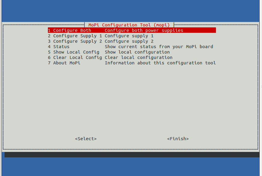
The
main entry screen.
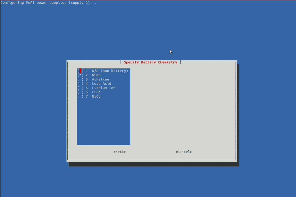
Configuring
one of the power supplies, battery chemistry.
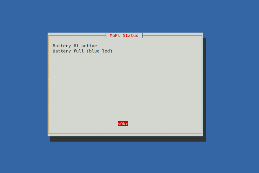
Getting
status data (there's lots more in the newest version!)
Dive into the source code here.
And now you know more about batteries than you ever wanted to — just like me!
4.5.Monitoring
As you can imagine, figuring out how all this stuff is working and identifying bugs and incorrect behaviour is quite a challenge. Luckily we have some great tools to help us, one of which is Monit. This little gem is itself a daemon, and it has facilities for one thousand and one different types of monitoring task. You can listen to your webserver and restart it if it fails, or check the general load of the machine you're running on, or — in our case — check that the simbamon service is running, and if not start it up.
To use it, all we need to do is sudo apt-get install monit in the usual way, then edit /etc/monit/monitrc. This is the config we're using to monitor simbamon on one of our test rigs:
###############################################################################
# monit config for simbamond, from /etc/monit/monitrc
#########################
# monitoring UI (serve on port 8888 and allow connections from one IP address)
set httpd port 8888 and
allow 192.168.1.111
# general system status
check system mopi-15
if loadavg (1min) > 4 then alert
if loadavg (5min) > 2 then alert
if memory usage > 75% then alert
if swap usage > 25% then alert
if cpu usage (user) > 70% then alert
if cpu usage (system) > 30% then alert
if cpu usage (wait) > 20% then alert
# monitor simbamond
check process simbamond with pidfile /var/run/simbamond.pid
start program = "/usr/sbin/service simbamond start" with timeout 60 seconds
stop program = "/usr/sbin/service simbamond stop"
restart program = "/usr/sbin/service simbamond restart" with timeout 60 seconds
if cpu > 60% for 2 cycles then alert
if cpu > 80% for 5 cycles then restart
if totalmem > 200.0 MB for 5 cycles then restart
if children > 250 then restart
if loadavg(5min) greater than 10 for 8 cycles then stop
if 3 restarts within 5 cycles then timeout
group mopi
###############################################################################
You can then see what's going on by either or both of
cat/var/log/monit.log (| grep simbamon is also useful)
pointing your browser at http://my-pi-ip-address:8888 (if you need to find your IP address various methods are discussed here)
This is great for keeping check on things during load testing (particularly heavy loads which have a tendency to cause odd corner case bugs to trigger), but it is also a great tool for maximizing service availability — the configuration code above will restart simbamon within a couple of minutes should it ever crash, for example.
4.6.simbamon: a simple battery monitor
4.6.1.Design Notes
There are a variety of ways that laptops communicate with and control their batteries, including the Smart Battery specification (which often uses SMBus, a variant of the I2C interface that the Pi supports). In Linux the resultant data feed is then modelled using a power management abstraction (of which ACPI is the most recent) and manipulated using a driver specific to the battery in use.
Sounds like a good idea? Yes, in the abstract, but implementing a new driver is quite a job — here's one that runs to 1200 lines of C code, for example. It is also not clear how to do this when we have the ability to plug in batteries of different types, which is something we really wanted to support.
What to do?
If in doubt, take the simple option. All Linux systems share the system service or daemon concept. A system-level process which gets run during startup. It is quite easy to implement a battery monitor daemon that listens on the Pi's I2C bus for level changes signaled by the MoPi-2 microcontroller board. The daemon then makes entries in the standard system logs as a simple way to share data with other subsystems, and can be configured to send a warning message to all users if levels are low. Best of all, the daemon can easily shut down the Pi cleanly before the regulator voltage gets too low for reliable operation.
4.6.2.Implementation
This section gives more detail of the implementation of the simbamon battery monitoring daemon. It is designed for the MoPi-2 boards, but should be quite easily reusable for other battery power projects. simbamon is an open source Linux daemon for:
Monitoring battery levels (for us this is done via the mopicli command)
Sending warning messages to the user if the battery is low
Shutting down cleanly at critical battery levels
Managing a power supply on/off switch
Writing relevant data to the system logs.
You can find the source code on GitHub. The core of the daemon is defined in three files:
/etc/init.d/simbamond — an interface to the init subsystem that Linux uses to manage daemons (amongst other things)
/usr/sbin/simbamon — the daemon itself
/etc/default/simbamond — configuration data
The first of these, simbamond, is used by the operating system to start and stop simbamon at boot or shutdown time, and can be used to control simbamon manually when required. For example this command will stop the daemon:
sudo service simbamond stop
The configuration file, (also) simbamond, defines how simbamon will take action. Of primary interest is the last few lines, which specifies the battery configuration in CLI format. There's some generic stuff at the top too about monitoring frequency and stuff, it's pretty well explained in the file.
###################################################################
# local config - DON'T EDIT THIS LINE!
# -wc 1 11200 10000 8800 8000
# end of local config - DON'T EDIT THIS LINE EITHER!
The MoPi-2 microcontroller supplies these states via the Raspberry Pi's I2C bus (and also sets on-board indicator LEDs accordingly). The core of simbamon, a shell script that lives in /usr/sbin/simbamon, implements an infinite loop that checks the levels being reported every few seconds and takes any necessary action. The wall command is used to send messages to any user currently logged in.
Here's a condensed version of the main loop (error checking, debug logging and other details omitted):
while :
do
# loop indices
i=$(( ${i} + 1 )); j=$(( ${j} + 1 ))
# get MoPi-2 status
MOPI_STATUS="`mopicli -nl -s`"
# action states (shutdown or warn)
if s_forced_shutdown "$MOPI_STATUS"
then
wall <<< "${NAME}: power off requested: shutting down now!!!"
logger "${NAME}: shutting down (POWER_OFF; ${MOPI_STATUS})"
eval "$SHUTDOWN"
elif s_bat_critical "$MOPI_STATUS"
then
wall <<< "${NAME}: battery empty: shutting down now!!!"
logger "${NAME}: shutting down (BAT_SHUTDOWN; ${MOPI_STATUS})"
eval "$SHUTDOWN"
elif s_bat_low "$MOPI_STATUS"
then
if [ $PREV_WARNING -eq 0 -o $(( $i - $PREV_WARNING )) -ge $WAIT_LOOPS ]
then
PREV_WARNING=$i
wall <<< "${NAME}: ${LMESS} is low! connect new battery or shut down"
logger "${NAME}: BAT_WARNING (${MOPI_STATUS})"
fi
fi
# routine log messages
[ "$DEBUG" = on -o ${j} -eq ${LOG_INTERVAL} ] && \
logger "${NAME}: ${LMESS} is ${MOPI_STATUS} at `pdate` (i=${i})" && j=0
# take a break
sleep ${MONITOR_FREQUENCY}
done &
Here is the current version of the code.
4.6.3.Installing Simbamon
The Raspbian maintainers have been kind enough to include simbamon in their repository, so you can just do this (as noted above):
sudo apt-get install simbamond
Our software is also available from an Ubuntu Personal Package Archive (PPA). (The Ubuntu infrastructure doesn't currently work for binary Pi packages, but simbamon and the rest of the MoPi-2 suite is implemented in script (shell and Python), so we're ok in this case.)8 To install from this archive:
1. Add this line to /etc/apt/ sources.list:
deb http://ppa.launchpad.net/hamish-dcs/pi-gate/ubuntu precise main
You can use a text editor (e.g. nano) to do this, or paste this one-liner into a terminal prompt:
echo deb http://ppa.launchpad.net/hamish-dcs/pi-gate/ubuntu precise
main |sudo tee -a /etc/apt/sources.list
2. Import the GPG encryption key from Ubuntu so that the Pi can verify the package's validity:
sudo apt-key adv --recv-keys --keyserver keyserver.ubuntu.com
--recv-key 6C12C1CF
3. Update your list of available packages (this may take a couple of minutes):
sudo apt-get update
4. Install the package:
sudo apt-get install simbamond
(You may ignore errors referring to module loading here — see above for details.)
And that's it!
Note: the above gets you the most recent stable release; if you want to live on the edge, you can get more recent experimental builds by adding the snapshot PPA to your sources list, e.g.:
echo deb http://ppa.launchpad.net/hamish-dcs/pi-gate-snapshots/
ubuntu precise main |sudo tee -a /etc/apt/sources.list
Footnotes
1. We quote a 6.5V to 24V max voltage to leave some headroom. We've run the board between 6.0V and 25V but don't recommend it as a general rule.
2. Ignore errors related to kmod.
3. Note that when MoPi-2 powers up the Pi, it then waits 60 seconds for the boot process to finish. During this period power off requests will be ignored.
4. Our Configuration Tool is a command line user interface, similar to raspi-config.
5. Confusingly the names of the files as they live in the source package are different from their names when installed. If you don't like being confused, you might want to avoid talking to computer people as a general rule. For example, the MoPi-2 board works on milivolts; the I2C communication uses centivolts; the user interface uses volts; the API uses milivolts. And all for good reasons!
6. And no one complained about the whitespace rules! Who'd have thought it?!
7. In common with most daemons, simbamon is written in shell script.
8. The main archive (for stable releases) is at https://launchpad.net/~hamish-dcs/+archive/pi-gate with a development snapshot archive at https://launchpad.net/~hamish-dcs/+archive/pi-gate-snapshots.